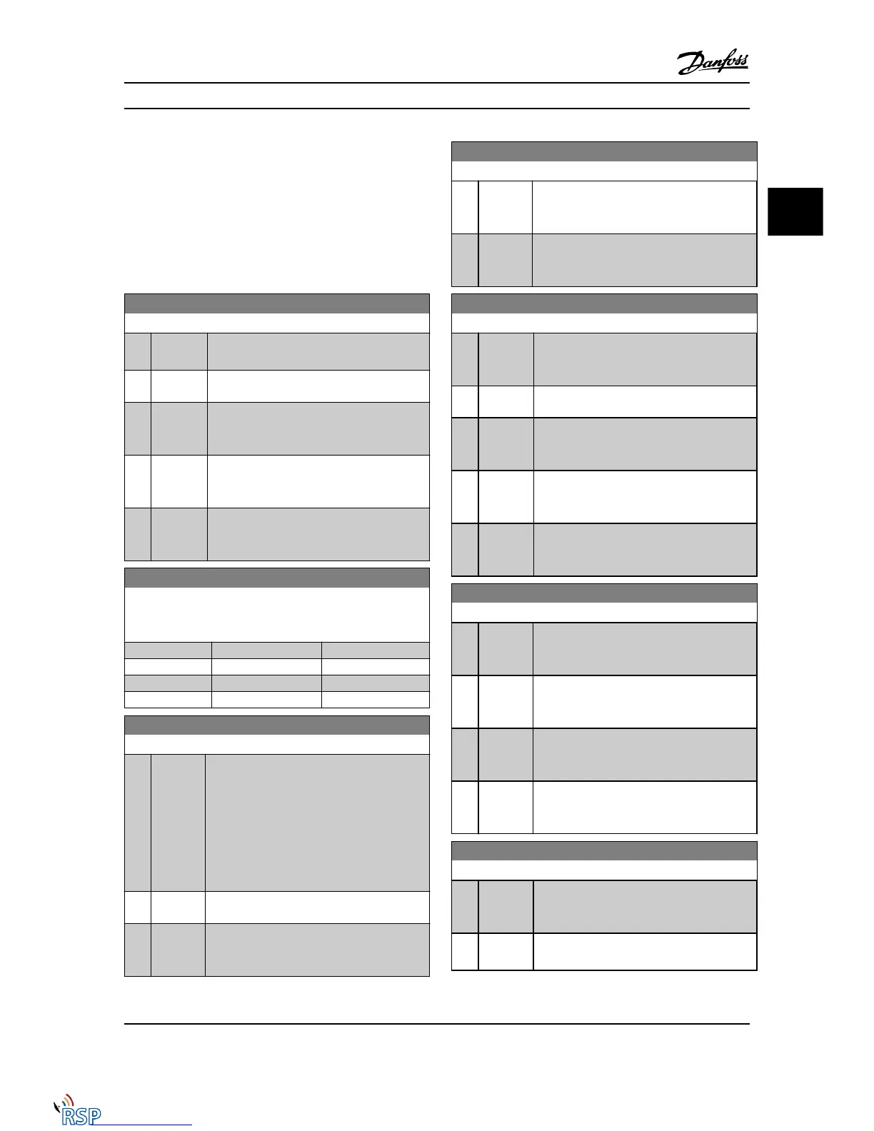
3.10.5 8-5* Digital/Bus
Parameters for configuring the control word Digital/Bus
merging.
NOTE!
These parameters are active only when 8-01 Control Site is
set to [0] Digital and control word.
8-50 Coasting Select
Option: Function:
Select control of the coasting function via the
terminals (digital input) and/or via the bus.
[0] Digital
input
Activates Start command via a digital input.
[1] Bus Activates Start command via the serial
communication port or serial communication
option.
[2] Logic AND Activates Start command via the serial
communication bus/serial communication port,
AND additionally via one of the digital inputs.
[3] * Logic OR Activates Start command via the serial
communication bus/serial communication port
OR via one of the digital inputs.
8-51 Quick Stop Select
Select control of the quick stop function via the terminals (digital
input) and/or via the bus.
Option: Function:
[0] Digital input
[1] Bus
[2] Logic AND
[3] * Logic OR
8-52 DC Brake Select
Option: Function:
Select control of the DC brake via the terminals
(digital input) and/or via the serial communi-
cation bus.
NOTE!
Only selection [0] Digital input is available
when 1-10 Motor Construction is set to [1]
PM non-salient SPM.
[0] Digital
input
Activates Start command via a digital input.
[1] Bus Activates Start command via the serial
communication port or serial communication
option.
8-52 DC Brake Select
Option: Function:
[2] Logic
AND
Activates Start command via the serial
communication bus/serial communication port,
AND additionally via one of the digital inputs.
[3] * Logic OR Activates Start command via the serial
communication bus/serial communication port
OR via one of the digital inputs.
8-53 Start Select
Option: Function:
Select control of the Adjustable frequency drive
start function via the terminals (digital input)
and/or via the serial communication bus.
[0] Digital
input
Activates Start command via a digital input.
[1] Bus Activates Start command via the serial
communication port or serial communication
option.
[2] Logic
AND
Activates Start command via the serial
communication bus/serial communication port,
AND additionally via one of the digital inputs.
[3] * Logic OR Activates Start command via the serial
communication bus/serial communication port
OR via one of the digital inputs.
8-54 Reversing Select
Option: Function:
[0] Digital
input
Select control of the Adjustable frequency drive
reverse function via the terminals (digital input)
and/or via the Serial communication bus.
[1] Bus Activates the Reverse command via the serial
communication port or Serial communication
bus option .
[2] Logic
AND
Activates the Reverse command via the Serial
communication bus/serial communication port,
AND additionally via one of the digital inputs.
[3] * Logic OR Activates the Reverse command via the Serial
communication bus/serial communication port
OR via one of the digital inputs.
8-55 Set-up Select
Option: Function:
Select control of the Adjustable frequency drive
set-up selection via the terminals (digital input)
and/or via the serial communication bus.
[0] Digital
input
Activates the set-up selection via a digital
input.
Parameter Descriptions FC 300 Programming Guide
MG33MD22 - VLT
®
is a registered Danfoss trademark 3-91
3
3

 Loading...


