Decrease or Clear. To activate the function, at least one
digital input must be set up to Increase or Decrease.
3-90 Step Size
Range: Function:
0.10 %* [0.01 - 200.00 %]
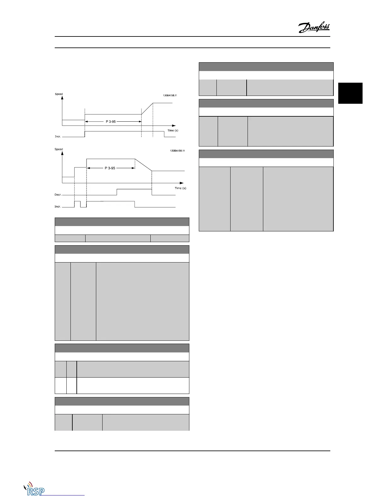
3-91 Ramp Time
Range: Function:
1.00
s*
[0.00 -
3600.00 s]
Enter the ramp time, i.e., the time for
adjustment of the reference from 0% to
100% of the specified digital potentiometer
function (Increase, Decrease or Clear).
If Increase/Decrease is activated for longer
than the ramp delay period specified in
3-95 Ramp Delay, the actual reference will be
ramped up/down according to this ramp
time. The ramp time is defined as the time
used to adjust the reference by the step size
specified in 3-90 Step Size.
3-92 Power Restore
Option: Function:
[0] * Off Resets the Digital Potentiometer reference to 0% after
power-up.
[1] On Restores the most recent Digital Potentiometer
reference at power-up.
3-93 Maximum Limit
Range: Function:
100 %* [-200 - 200
%]
Set the maximum permissible value for
the resultant reference. This is advisable if
3-93 Maximum Limit
Range: Function:
the Digital Potentiometer is used for fine
tuning of the resulting reference.
3-94 Minimum Limit
Range: Function:
-100 %* [-200 - 200
%]
Set the minimum permissible value for
the resultant reference. This is advisable
if the Digital Potentiometer is used for
fine tuning of the resulting reference.
3-95 Ramp Delay
Range: Function:
Application
dependent*
[Application
dependant]
Enter the delay required from
activation of the digital potenti-
ometer function until the
Adjustable frequency drive starts
to ramp the reference. With a
delay of 0 ms, the reference
starts to ramp as soon as
INCREASE/DECREASE is activated.
See also 3-91 Ramp Time.
Parameter Descriptions FC 300 Programming Guide
MG33MD22 - VLT
®
is a registered Danfoss trademark 3-43
3
3

 Loading...


