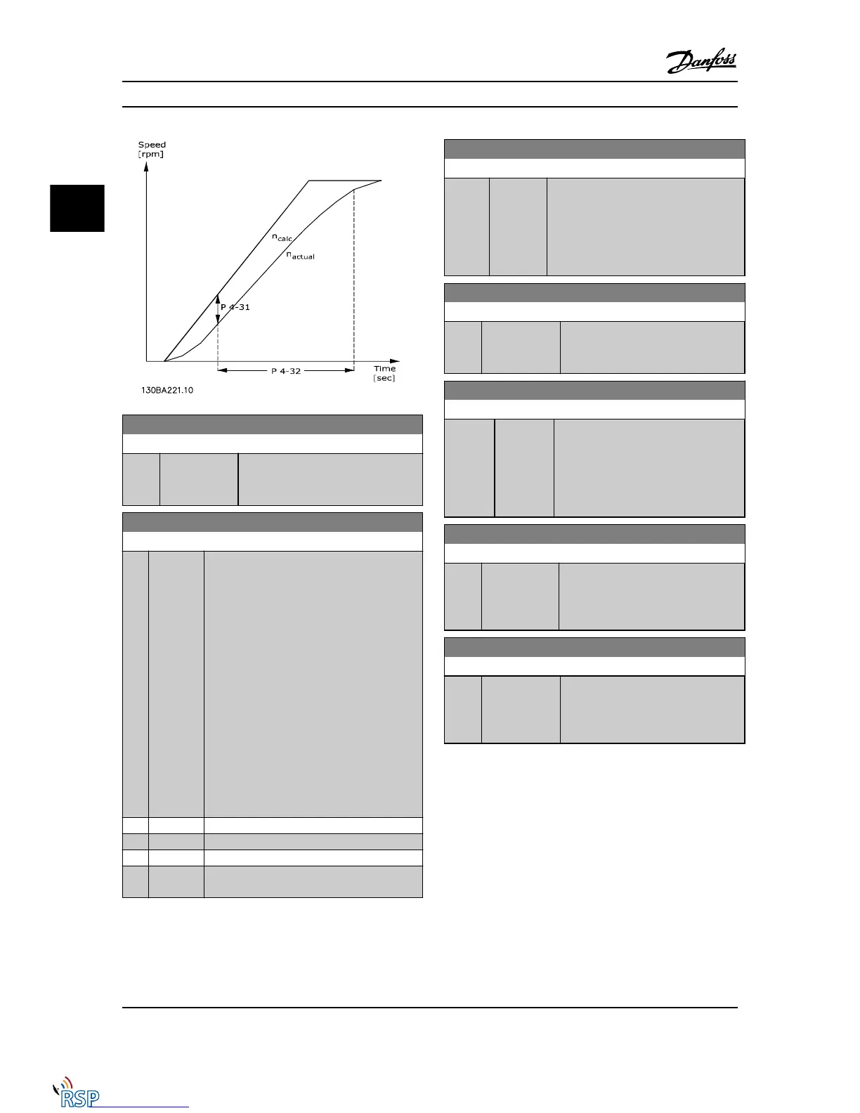
4-32 Motor Feedback Loss Timeout
Range: Function:
0.05 s* [0.00 - 60.00 s] Set the timeout value allowing the
speed error set in 4-31 Motor Feedback
Speed Error to be exceeded.
4-34 Tracking Error Function
Option: Function:
Select which reaction the Adjustable frequency
drive should take if a tracking error is detected.
Closed-loop: The tracking error is measured
between the output from the ramp generator
and the speed feedback (filtered).
Open-loop: The tracking error is measured
between the output from the ramp generator -
compensated for slip - and the frequency that
is sent to the motor (16-13 Frequency).
The reaction will be activated if the measured
difference is more than specified in
4-35 Tracking Error for the time specified in
4-36 Tracking Error Timeout.
A tracking error in closed-loop does not imply
that there is a problem with the feedback
signal! A tracking error can be the result of
torque limit for loads that are too big.
[0] * Disable
[1] Warning
[2] Trip
[3] Trip after
stop
Warning/Alarm 78 Tracking Error is related to the Tracking
Error Function.
4-35 Tracking Error
Range: Function:
10 RPM* [1 - 600
RPM]
Enter the maximum permissible speed
error between the motor speed and the
output of the ramp when not ramping. In
open-loop, the motor speed is estimated,
and in closed-loop, it is the feedback from
encoder/resolver.
4-36 Tracking Error Timeout
Range: Function:
1.00 s* [0.00 - 60.00 s] Enter the timeout period during which
an error greater than the value set in
4-35 Tracking Error is permissible.
4-37 Tracking Error Ramping
Range: Function:
100 RPM* [1 - 600
RPM]
Enter the maximum permissible speed
error between the motor speed and the
output of the ramp when ramping. In
open-loop, the motor speed is estimated,
and in closed-loop, it is the feedback
from encoder/resolver.
4-38 Tracking Error Ramping Timeout
Range: Function:
1.00 s* [0.00 - 60.00
s]
Enter the timeout period during which
an error greater than the value set in
4-37 Tracking Error Ramping while
ramping is permissible.
4-39 Tracking Error After Ramping Timeout
Range: Function:
5.00 s* [0.00 - 60.00 s] Enter the timeout period after ramping
where 4-37 Tracking Error Ramping and
4-38 Tracking Error Ramping Timeout are
still active.
3.6.3 4-5* Adjustable Warnings
Use these parameters to adjust warning limits for current,
speed, reference and feedback. Warnings that are shown
on the display can be programmed as an output or sent
via serial bus.
Warnings are shown on display, programmed output or
serial bus.
Parameter Descriptions FC 300 Programming Guide
3-46 MG33MD22 - VLT
®
is a registered Danfoss trademark
3
3

 Loading...


