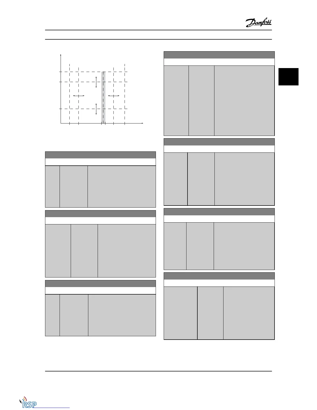
Figure 3.9 Adjustable Warnings
4-50 Warning Current Low
Range: Function:
0.00 A* [Application
dependant]
Enter the I
LOW
value. When the motor
current falls below this limit, the display
reads Current Low. The signal outputs
can be programmed to produce a
status signal on terminal 27 or 29 (FC
302 only) and on relay output 01 or 02
(FC 302 only). Refer to Figure 3.9.
4-51 Warning Current High
Range: Function:
Application
dependent*
[Application
dependant]
Enter the I
HIGH
value. When the
motor current exceeds this limit,
the display reads Current High.
The signal outputs can be
programmed to produce a status
signal on terminal 27 or 29 (FC
302 only) and on relay output 01
or 02 (FC 302 only). Refer to
Figure 3.9.
4-52 Warning Speed Low
Range: Function:
0 RPM* [Application
dependant]
Enter the n
LOW
value. When the motor
speed exceeds this limit, the display
reads Speed Low. The signal outputs
can be programmed to produce a
status signal on terminal 27 or 29 (FC
302 only) and on relay output 01 or 02
(FC 302 only).
4-53 Warning Speed High
Range: Function:
Application
dependent*
[Application
dependant]
Enter the n
HIGH
value. When the
motor speed exceeds this limit, the
display reads Speed High. The
signal outputs can be
programmed to produce a status
signal on terminal 27 or 29 (FC
302 only) and on relay output 01
or 02 (FC 302 only). Program the
upper signal limit of the motor
speed, n
HIGH
, within the normal
working range of the Adjustable
frequency drive. Refer to Figure 3.9.
4-54 Warning Reference Low
Range: Function:
-999999.999* [Application
dependant]
Enter the lower reference limit.
When the actual reference falls
below this limit, the display
indicates Ref Low. The signal
outputs can be programmed to
produce a status signal on
terminal 27 or 29 (FC 302 only)
and on relay output 01 or 02 (FC
302 only).
4-55 Warning Reference High
Range: Function:
999999.999* [Application
dependant]
Enter the upper reference limit.
When the actual reference exceeds
this limit, the display reads Ref
High. The signal outputs can be
programmed to produce a status
signal on terminal 27 or 29 (FC 302
only) and on relay output 01 or 02
(FC 302 only).
4-56 Warning Feedback Low
Range: Function:
-999999.999
ReferenceFeed-
backUnit*
[Application
dependant]
Enter the lower feedback
limit. When the feedback falls
below this limit, the display
reads Feedb Low. The signal
outputs can be programmed
to produce a status signal on
terminal 27 or 29 (FC 302
only) and on relay output 01
or 02 (FC 302 only).
Parameter Descriptions FC 300 Programming Guide
MG33MD22 - VLT
®
is a registered Danfoss trademark 3-47
3
3

 Loading...


