5-40 Function Relay
Array [9]
(Relay 1 [0], Relay 2 [1], Relay 3 [2] (MCB 113), Relay 4 [3] (MCB
113), Relay 5 [4] (MCB 113), Relay 6 [5] (MCB 113), Relay 7 [6]
(MCB 105), Relay 8 [7] (MCB 105), Relay 9 [8] (MCB 105))
Option: Function:
[151] ATEX ETR cur. alarm
Selectable if 1-90 Motor Thermal
Protection is set to [20] or [21]. If the
alarm 164 ATEX ETR cur.lim.alarm is
active, the output will be 1.
[152] ATEX ETR freq.
alarm
Selectable if 1-90 Motor Thermal
Protection is set to [20] or [21]. If the
alarm 166 ATEX ETR freq.lim.alarm is
active, the output will be 1.
[153] ATEX ETR cur.
warning
Selectable if 1-90 Motor Thermal
Protection is set to [20] or [21]]. If the
alarm 163 ATEX ETR cur.lim.warning
is active, the output will be 1.
[154] ATEX ETR freq.
warning
Selectable if 1-90 Motor Thermal
Protection is set to [20] or [21]. If the
warning 165 ATEX ETR
freq.lim.warning is active, the output
will be 1.
[188] AHF Capacitor
Connect
[189] External Fan Control The internal logics for the internal
fan control is transferred to this
output to make it possible to control
an external fan (relevant for HP duct
cooling).
[192] RS Flipflop 0
[193] RS Flipflop 1
[194] RS Flipflop 2
[195] RS Flipflop 3
[196] RS Flipflop 4
[197] RS Flipflop 5
[198] RS Flipflop 6
[199] RS Flipflop 7
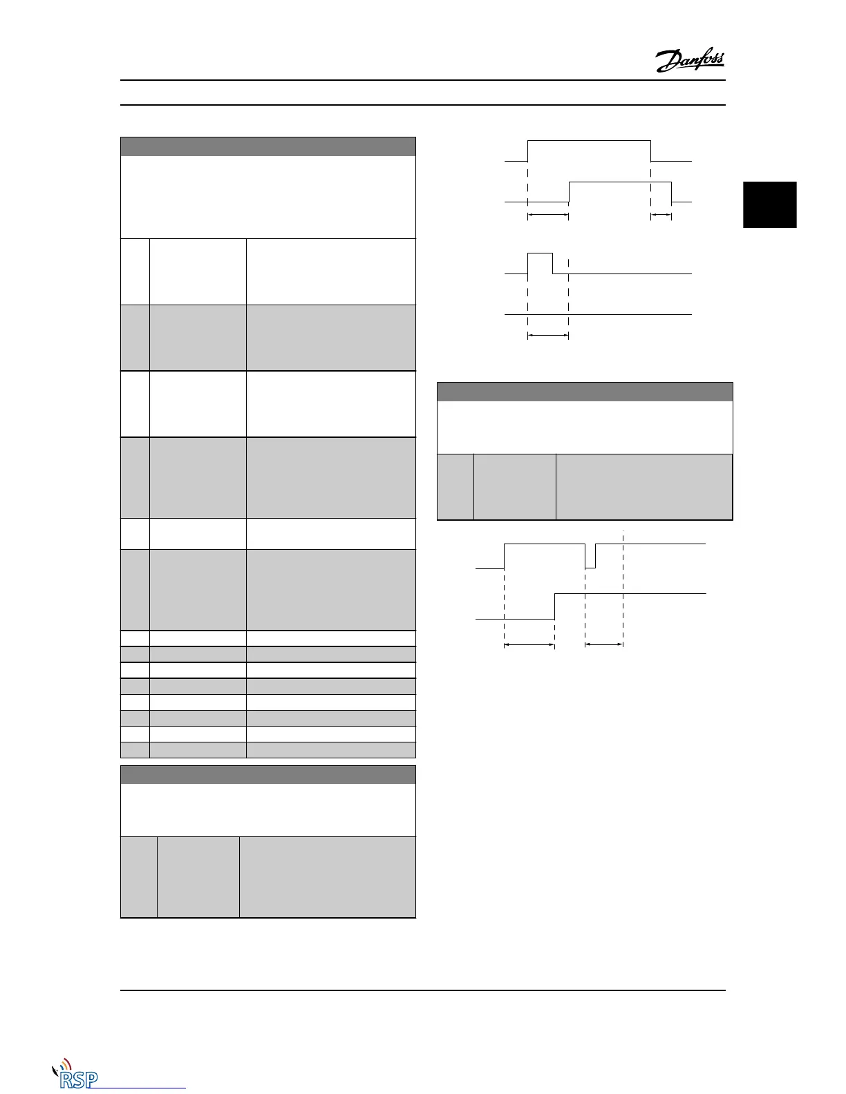
5-41 On Delay, Relay
Array [9], (Relay 1 [0], Relay 2 [1], Relay 3 [2], Relay 4 [3], Relay 5
[4], Relay 6 [5], Relay 7 [6], Relay 8 [7], Relay 9 [8])
Range: Function:
0.01 s* [0.01 - 600.00 s] Enter the delay of the relay cut-in
time. Select one of available
mechanical relays and MCB 105 in an
array function. See 5-40 Function Relay.
Relay 3-6 are included in MCB 113.
5-42 Off Delay, Relay
Array [9] (Relay 1 [0], Relay 2 [1], Relay 3 [2], Relay 4 [3], Relay 5
[4], Relay 6 [5], Relay 7 [6], Relay 8 [7], Relay 9 [8])
Range: Function:
0.01 s* [0.01 - 600.00 s] Enter the delay of the relay cut-out
time. Select one of available
mechanical relays and MCB 105 in an
array function. See 5-40 Function Relay.
If the selected event condition changes before the on or
off delay timer expires, the relay output is unaffected.
3.7.5
5-5* Pulse Input
The pulse input parameters are used to define an
appropriate window for the impulse reference area by
configuring the scaling and filter settings for the pulse
inputs. Input terminals 29 or 33 act as frequency reference
inputs. Set terminal 29 (5-13 Terminal 29 Digital Input) or
terminal 33 (5-15 Terminal 33 Digital Input) to Pulse input
[32]. If terminal 29 is used as an input, then set
5-01 Terminal 27 Mode to Input [0].
Parameter Descriptions FC 300 Programming Guide
MG33MD22 - VLT
®
is a registered Danfoss trademark 3-63
3
3

 Loading...


