3.10 Parameters: 8-** Communications and
Options
3.10.1 8-0* General Settings
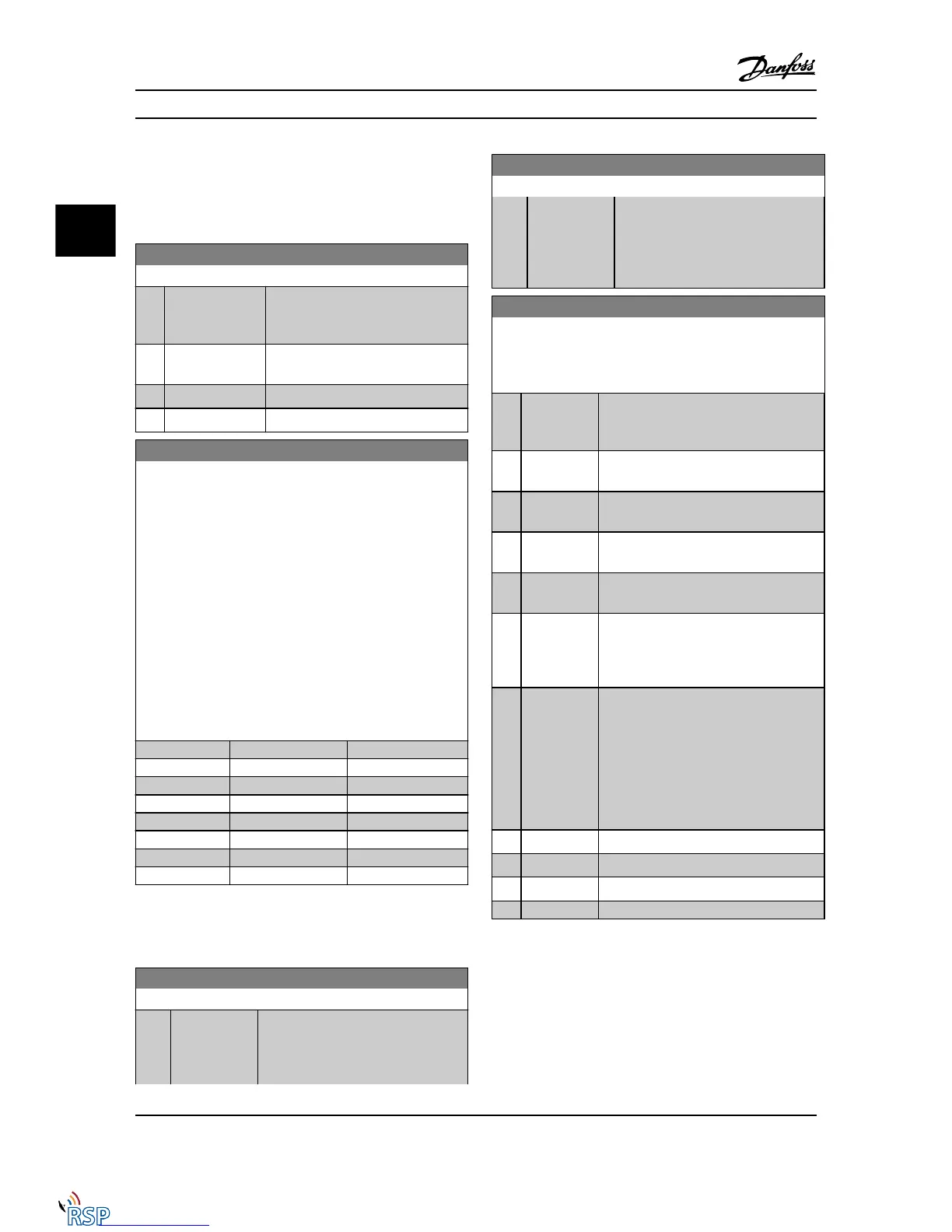
8-01 Control Site
Option: Function:
The setting in this parameter overrides
the settings in 8-50 Coasting Select to
8-56 Preset Reference Select.
[0] * Digital and
ctrl.word
Control by using both digital input and
control word.
[1] Digital only Control by using digital inputs only.
[2] Controlword only Control by using control word only.
8-02 Control Word Source
Select the source of the control word: one of two serial interfaces
or four installed options. During initial power-up, the Adjustable
frequency drive automatically sets this parameter to Option A [3]
if it detects a valid Serial communication bus option installed in
slot A. If the option is removed, the Adjustable frequency drive
detects a change in the configuration, sets 8-02 Control Word
Source back to default setting RS-485, and the Adjustable
frequency drive then trips. If an option is installed after initial
power-up, the setting of 8-02 Control Word Source will not
change but the Adjustable frequency drive will trip and display:
Alarm 67 Option Changed.
When you retrofit a bus option into a Adjustable frequency drive
that did not have a bus option installed to begin with, you must
take an ACTIVE decision to move the control to bus-based. This
is done for safety reasons in order to avoid an accidental change.
Option: Function:
[0] None
[1] FC RS485
[2] FC USB
[3] * Option A
[4] Option B
[5] Option C0
[6] Option C1
[30] External Can
NOTE!
This parameter cannot be adjusted while the motor is
running.
8-03 Control Word Timeout Time
Range: Function:
1.0 s* [Application
dependant]
Enter the maximum time expected to
pass between the reception of two
consecutive messages. If this time is
exceeded, it indicates that the serial
8-03 Control Word Timeout Time
Range: Function:
communication has stopped. The
function selected in 8-04 Control Word
Timeout Function will then be carried
out. The timeout counter is triggered by
a valid control word.
8-04 Control Word Timeout Function
Select the timeout function. The timeout function activates when
the control word fails to be updated within the time period
specified in 8-03 Control Word Timeout Time.
Option: Function:
[0] * Off Resumes control via serial bus (Serial
communication bus or standard) using the
most recent control word.
[1] Freeze output Freezes output frequency until communi-
cation resumes.
[2] Stop Stops with auto-restart when communi-
cation resumes.
[3] Jogging Runs the motor at JOG frequency until
communication resumes.
[4] Max. speed Runs the motor at maximum frequency
until communication resumes.
[5] Stop and trip Stops the motor, then resets the Adjustable
frequency drive in order to restart: via the
Serial communication bus, via the reset
button on the LCP or via a digital input.
[7] Select setup 1 Changes the set-up upon reestablishment of
communication following a control word
timeout. If communication resumes causing
the timeout situation to disappear,
8-05 End-of-Timeout Function defines
whether to resume the set-up used before
the timeout or to retain the set-up
endorsed by the timeout function.
[8] Select setup 2
See [7] Select setup 1
[9] Select setup 3
See [7] Select setup 1
[10] Select setup 4
See [7] Select setup 1
[26] Trip
NOTE!
The following configuration is required in order to change
the set-up after a timeout:
Set 0-10 Active Set-up to [9] Multi set-up and select the
relevant link in 0-12 This Set-up Linked to.
Parameter Descriptions FC 300 Programming Guide
3-84 MG33MD22 - VLT
®
is a registered Danfoss trademark
3
3

 Loading...


