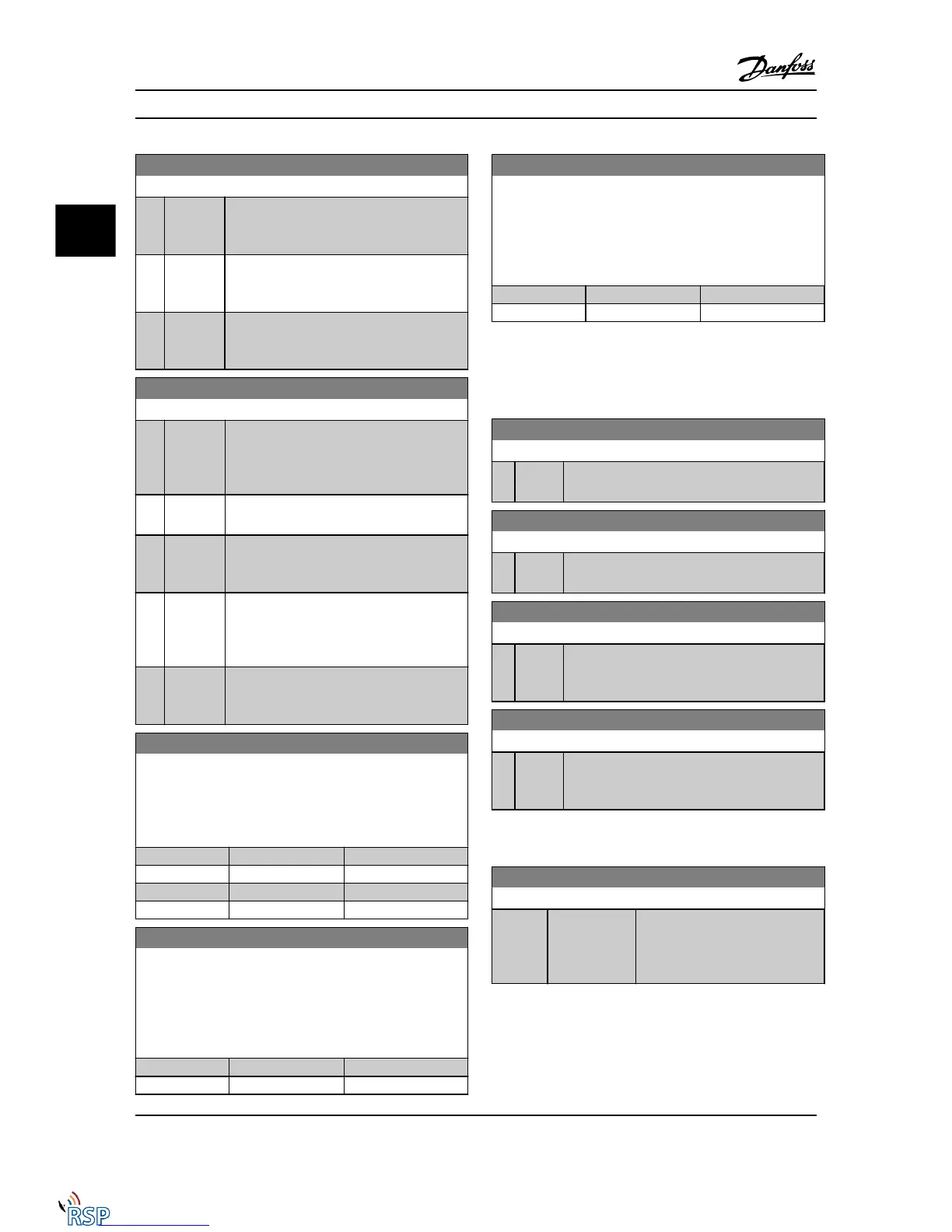
8-55 Set-up Select
Option: Function:
[1] Bus Activates the set-up selection via the serial
communication port or serial communication
option.
[2] Logic
AND
Activates the set-up selection via the serial
communication bus/serial communication port,
AND additionally via one of the digital inputs.
[3] * Logic OR Activate the set-up selection via the serial
communication bus/serial communication port
OR via one of the digital inputs.
8-56 Preset Reference Select
Option: Function:
Select control of the Adjustable frequency drive
Preset Reference selection via the terminals
(digital input) and/or via the serial communi-
cation bus.
[0] Digital
input
Activates Preset Reference selection via a digital
input.
[1] Bus Activates Preset Reference selection via the
serial communication port or serial communi-
cation option.
[2] Logic AND Activates Preset Reference selection via the
serial communication bus/serial communication
port, AND additionally via one of the digital
inputs.
[3] * Logic OR Activates the Preset Reference selection via the
serial communication bus/serial communication
port OR via one of the digital inputs.
8-57 Profidrive OFF2 Select
Select control of the drive OFF2 selection via the terminals
(digital input) and/or via the serial communication bus. This
parameter is active only when par. 8-01 Control Site is set to [0]
Digital and ctrl. word and par. 8-10 is set to [1] Profidrive profile.
Option: Function:
[0] Digital input
[1] Bus
[2] Logic AND
[3] * Logic OR
8-58 Profidrive OFF3 Select
Select control of the drive OFF3 selection via the terminals
(digital input) and/or via the serial communication bus. This
parameter is active only when par. 8-01 Control Site is set to [0]
Digital and control word and par. 8-10 is set to [1] Profidrive
profile.
Option: Function:
[0] Digital input
[1] Bus
8-58 Profidrive OFF3 Select
Select control of the drive OFF3 selection via the terminals
(digital input) and/or via the serial communication bus. This
parameter is active only when par. 8-01 Control Site is set to [0]
Digital and control word and par. 8-10 is set to [1] Profidrive
profile.
Option: Function:
[2] Logic AND
[3] * Logic OR
3.10.6 8-8* AFD Port Diagnos.
These parameters are used for monitoring the bus
communication via the Adjustable Frequency Drive Port.
8-80 Bus Message Count
Range: Function:
0 * [0 - 0 ] This parameter shows the number of valid
messages detected on the bus.
8-81 Bus Error Count
Range: Function:
0 * [0 - 0 ] This parameter shows the number of messages
with faults (e.g., CRC fault), detected on the bus.
8-82 Slave Messages Rcvd
Range: Function:
0 * [0 - 0 ] This parameter shows the number of valid
messages addressed to the slave, sent by the
Adjustable frequency drive.
8-83 Slave Error Count
Range: Function:
0 * [0 - 0 ] This parameter shows the number of error
messages, which could not be executed by the
Adjustable frequency drive.
3.10.7 8-9* Bus Jog
8-90 Bus Jog 1 Speed
Range: Function:
100 RPM* [ 0 - par. 4-13
RPM]
Enter the jog speed. This is a fixed
jog speed activated via the serial
port or serial communication bus
option.
Parameter Descriptions FC 300 Programming Guide
3-92 MG33MD22 - VLT
®
is a registered Danfoss trademark
3
3

 Loading...


