5 Troubleshooting
5.1.1 Warnings/Alarm Messages
A warning or an alarm is signaled by the relevant LED on
the front of the Adjustable frequency drive and indicated
by a code on the display.
A warning remains active until its cause is no longer
present. Under certain circumstances operation of the
motor may still be continued. Warning messages may be
critical, but are not necessarily so.
In the event of an alarm, the Adjustable frequency drive
will have tripped. Alarms must be reset to restart operation
once their cause has been rectified.
This may be done in three ways:
1. By using the [RESET] control button on the LCP.
2. Via a digital input with the “Reset” function.
3. Via serial communication/optional serial
communication bus.
NOTE!
After a manual reset using the [RESET] button on the LCP,
the [AUTO ON] button must be pressed to restart the
motor.
If an alarm cannot be reset, the reason may be that its
cause has not been rectified, or the alarm is trip-locked
(see also table on following page).
Alarms that are trip-locked offer additional protection,
meaning that the line power supply must be switched off
before the alarm can be reset. After being switched back
on, the Adjustable frequency drive is no longer blocked
and may be reset as described above once the cause has
been rectified.
Alarms that are not trip-locked can also be reset using the
automatic reset function in 14-20 Reset Mode (Warning:
automatic wake-up is possible!)
If a warning and alarm are marked against a code in the
table on the following page, this means that either a
warning occurs before an alarm, or that you can specify
whether it is a warning or an alarm that is to be displayed
for a given fault.
This is possible, for instance, in 1-90 Motor Thermal
Protection. After an alarm or trip, the motor carries on
coasting, and the alarm and warning flash. Once the
problem has been rectified, only the alarm continues
flashing until the Adjustable frequency drive is reset.
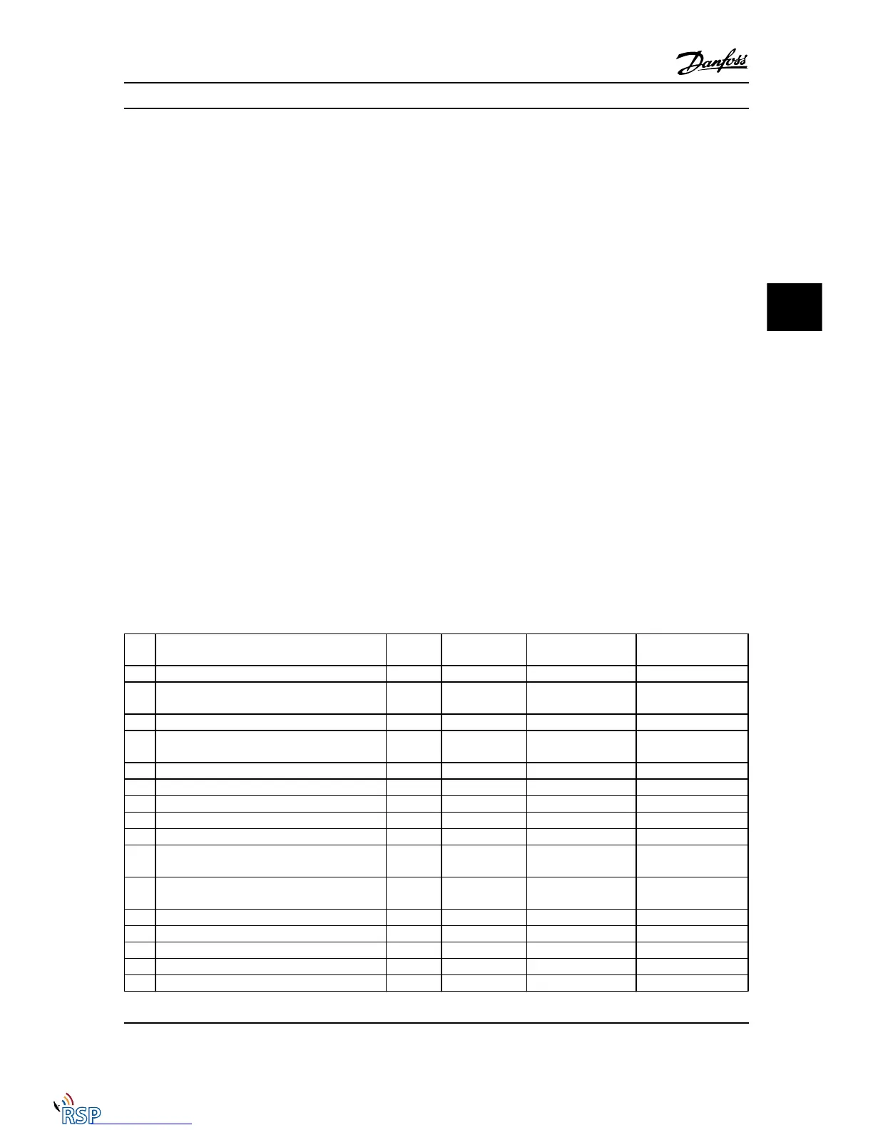
No. Description Warning Alarm/Trip Alarm/Trip Lock Parameter
Reference
1 10 Volts low X
2 Live zero error (X) (X)
6-01 Live Zero Timeout
Function
3 No motor (X)
1-80 Function at Stop
4 Line phase loss (X) (X) (X)
14-12 Function at Mains
Imbalance
5 DC link voltage high X
6 DC link voltage low X
7 DC overvoltage X X
8 DC under-voltage X X
9 Inverter overloaded X X
10 Motor ETR over-temperature (X) (X)
1-90 Motor Thermal
Protection
11 Motor thermistor over-temperature (X) (X)
1-90 Motor Thermal
Protection
12 Torque limit X X
13 Overcurrent X X X
14 Ground Fault X X X
15 Hardware mismatch X X
16 Short Circuit X X
Troubleshooting FC 300 Programming Guide
MG33MD22 - VLT
®
is a registered Danfoss trademark 5-1
5 5

 Loading...


