1-53 Model Shift Frequency
Range: Function:
With this parameter it is possible to
make an adjustment of the shifting
point where FC 302 changes
between Flux model 1 and Flux
model 2, which is useful in some
sensitive speed and torque control
applications.
Figure 3.2 1-00 Configuration
Mode = [1] Speed closed-loop or
[2] Torque and 1-01 Motor Control
Principle = [3] Flux w/motor
feedback
Variable Current - Flux model -
Sensorless
This model is used when
1-00 Configuration Mode is set to
Speed open-loop [0] and 1-01 Motor
Control Principle is set to Flux
sensorless [2].
In speed open-loop in flux mode,
the speed is determined by the
current measurement.
Below f
norm
x 0.1, the Adjustable
frequency drive runs on a variable
current model. Above f
norm
x 0.125
the Adjustable frequency drive runs
on a flux model.
Figure 3.3 1-00 Configuration
Mode = [0] Speed open-loop,
1-01 Motor Control Principle = [2]
Flux sensorless
1-54 Voltage reduction in fieldweakening
Range: Function:
0 V* [0 - 100
V]
The value of this parameter will reduce the
maximal voltage available for the flux of the
1-54 Voltage reduction in fieldweakening
Range: Function:
motor in fieldweakening, giving more voltage
available for torque. Be aware that a value that
is too high may cause stalling problems at high
speed.
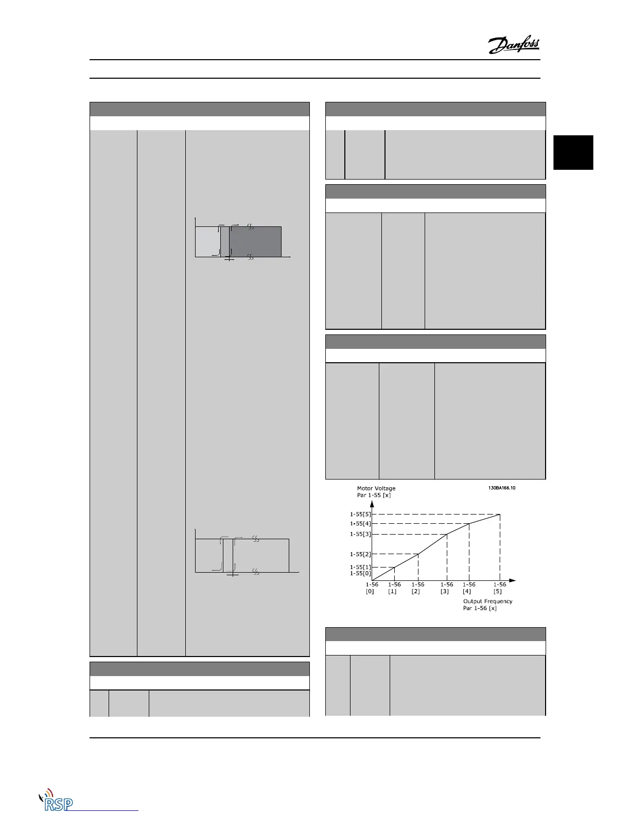
1-55 U/f Characteristic - U
Range: Function:
Application
dependent*
[0.0 -
1000.0 V]
Enter the voltage at each
frequency point to manually form a
U/f characteristic matching the
motor.
The frequency points are defined
in 1-56 U/f Characteristic - F.
This parameter is an array
parameter [0-5] and is only
accessible when 1-01 Motor Control
Principle is set to U/f [0].
1-56 U/f Characteristic - F
Range: Function:
Application
dependent*
[Application
dependant]
Enter the frequency points to
manually form a U/f-charac-
teristic matching the motor.
The voltage at each point is
defined in 1-55 U/f Characteristic
- U.
This parameter is an array
parameter [0-5] and is only
accessible when 1-01 Motor
Control Principle is set to U/f [0].
1-58 Flystart Test Pulses Current
Range: Function:
30 %* [0 - 200
%]
Control the percentage of the magnetizing
current for the pulses used to detect the
motor direction. Reducing this value will
reduce the generated torque. 100% means
nominal motor current. The parameter is
Parameter Descriptions FC 300 Programming Guide
MG33MD22 - VLT
®
is a registered Danfoss trademark 3-19
3
3

 Loading...


