3.7 Parameters: 5-** Digital In/Out
3.7.1 5-0* Digital I/O Mode
Parameters for configuring the input and output using
NPN and PNP.
5-00 Digital I/O Mode
Option: Function:
Digital inputs and programmed digital outputs are
pre-programmable for operation either in PNP or NPN
systems.
[0] * PNP
Action on positive directional pulses (↕). PNP systems
are pulled down to GND.
[1] NPN
Action on negative directional pulses (↕). NPN
systems are pulled up to + 24V, internally in the
Adjustable frequency drive.
NOTE!
Once this parameter has been changed, it must be
activated by performing a power cycle.
5-01 Terminal 27 Mode
Option: Function:
[0] * Input Defines terminal 27 as a digital input.
[1] Output Defines terminal 27 as a digital output.
5-02 Terminal 29 Mode
Option: Function:
[0] * Input Defines terminal 29 as a digital input.
[1] Output Defines terminal 29 as a digital output.
This parameter is available for FC 302 only.
3.7.2
Digital Inputs
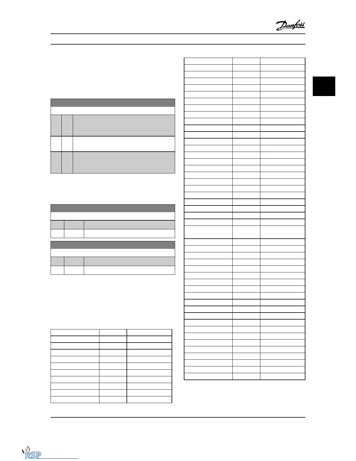
The digital inputs are used for selecting various functions
in the Adjustable frequency drive. All digital inputs can be
set to the following functions:
Digital input function Select Terminal
No operation [0] All *term 32, 33
Reset [1] All
Coast inverse [2] All *term 27
Coast and reset inverse [3] All
Quick stop inverse [4] All
DC brake inverse [5] All
Stop inverse [6] All
Start [8] All *term 18
Latched start [9] All
Reversing [10] All *term 19
Digital input function Select Terminal
Start reversing [11] All
Enable start forward [12] All
Enable start reverse [13] All
Jog [14] All *term 29
Preset reference on [15] All
Preset ref bit 0 [16] All
Preset ref bit 1 [17] All
Preset ref bit 2 [18] All
Freeze reference [19] All
Freeze output [20] All
Speed up [21] All
Slow [22] All
Set-up select bit 0 [23] All
Set-up select bit 1 [24] All
Precise stop inverse [26] 18, 19
Precise start, stop [27] 18, 19
Catch up [28] All
Slow-down [29] All
Counter input [30] 29, 33
Pulse input Edge Trigged [31] 29, 33
Pulse input Time Based [32] 29, 33
Ramp bit 0 [34] All
Ramp bit 1 [35] All
Latched precise start [40] 18, 19
Latched precise stop
inverse
[41] 18, 19
External interlock [51]
DigiPot Increase [55] All
DigiPot Decrease [56] All
DigiPot Clear [57] All
Digipot Hoist [58] All
Counter A (up) [60] 29, 33
Counter A (down) [61] 29, 33
Reset Counter A [62] All
Counter B (up) [63] 29, 33
Counter B (down) [64] 29, 33
Reset Counter B [65] All
Mech. Brake Feedb. [70] All
Mech. Brake Feedb. Inv. [71] All
PID Error Inv. [72] All
PID Reset I-part [73] All
PID enable [74] All
PTC Card 1 [80] All
Profidrive OFF2 [91]
Profidrive OFF3 [92]
Start edge triggered [98]
Safe Option Reset [100]
FC 300 standard terminals are 18, 19, 27, 29, 32 and 33.
MCB 101 terminals are X30/2, X30/3 and X30/4.
Terminal 29 functions as an output only in FC 302.
Parameter Descriptions FC 300 Programming Guide
MG33MD22 - VLT
®
is a registered Danfoss trademark 3-49
3
3

 Loading...


