3.14 Parameters: 13-** Smart Logic Control
3.14.1 Prog. Features
Smart Logic Control (SLC) is essentially a sequence of user-
defined actions (see 13-52 SL Controller Action [x]) executed
by the SLC when the associated user-defined event (see
13-51 SL Controller Event [x]) is evaluated as TRUE by the
SLC .
The condition for an event can be a particular status or
that the output from a logic rule or a comparator operand
becomes TRUE. That will lead to an associated action as
illustrated:
Events and actions are each numbered and linked together
in pairs (states). This means that when event [0] is fulfilled
(attains the value TRUE), action [0] is executed. After this,
the conditions of event [1] will be evaluated and if
evaluated TRUE, action [1] will be executed and so on.
Only one event will be evaluated at any time. If an event is
evaluated as FALSE, nothing happens (in the SLC) during
the current scan interval and no other events will be
evaluated. This means that when the SLC starts, it
evaluates event [0] (and only event [0]) each scan interval.
Only when event [0] is evaluated TRUE, will the SLC
execute action [0] and start evaluating event [1]. It is
possible to program from 1 to 20 events and actions.
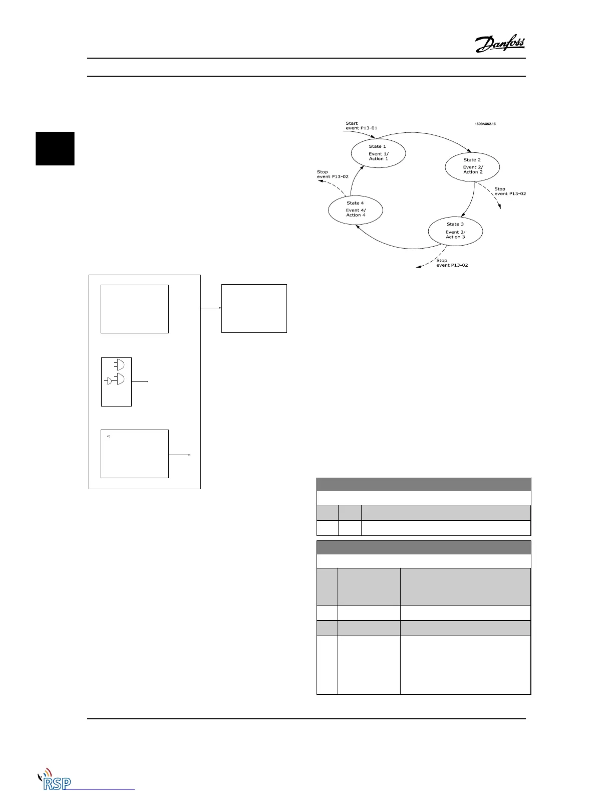
When the last event / action has been executed, the
sequence starts over again from event [0] / action [0]. The
figure shows an example with three events/actions:
Starting and stopping the SLC:
Starting and stopping the SLC can be done by
selecting .On [1]. or .Off [0]. in 13-00 SL Controller Mode.
The SLC always starts in state 0 (where it evaluates event
[0]). The SLC starts when the Start Event (defined in
13-01 Start Event) is evaluated as TRUE (provided that On
[1] is selected in 13-00 SL Controller Mode). The SLC stops
when the Stop Event (13-02 Stop Event) is TRUE. 13-03 Reset
SLC resets all SLC parameters and start programming from
scratch.
3.14.2
13-0* SLC Settings
Use the SLC settings to activate, deactivate and reset the
Smart Logic Control sequence. The logic functions and
comparators are always running in the background, which
opens for separate control of digital inputs and outputs.
13-00 SL Controller Mode
Option: Function:
[0] Off Disables the Smart Logic Controller.
[1] On Enables the Smart Logic Controller.
13-01 Start Event
Option: Function:
[0] * False Select the Boolean (TRUE or FALSE)
input to activate Smart Logic Control.
False [0] enters the fixed value - FALSE
[1] True
True [1] enters the fixed value - TRUE.
[2] Running
Running [2] The motor is running.
[3] In range
In range [3] The motor is running
within the programmed current and
speed ranges set in 4-50 Warning
Current Low to 4-53 Warning Speed
High.
Parameter Descriptions FC 300 Programming Guide
3-110 MG33MD22 - VLT
®
is a registered Danfoss trademark
3
3

 Loading...


