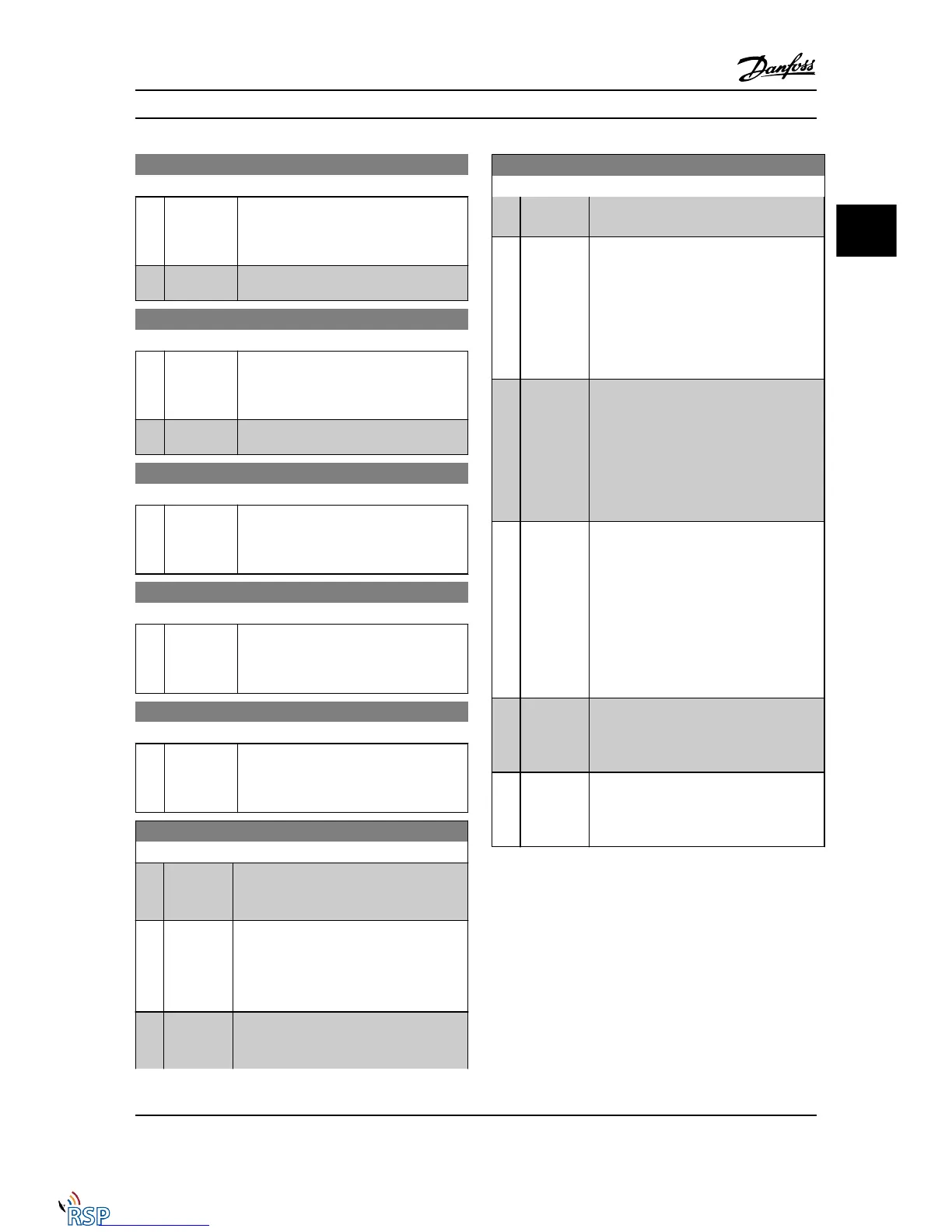
5-14 Terminal 32 Digital Input
Option: Function:
Select the function from the available digital
input range and the additional options [60],
[61], [63] and [64]. Counters are used in
Smart Logic Control functions.
[0] * No operation
Functions are described under 5-1* Digital
Inputs
5-15 Terminal 33 Digital Input
Option: Function:
Select the function from the available digital
input range and the additional options [60],
[61], [63] and [64]. Counters are used in
Smart Logic Control functions.
[0] * No operation
Functions are described under 5-1* Digital
Inputs
5-16 Terminal X30/2 Digital Input
Option: Function:
[0] * No operation This parameter is active when option module
MCB101 is installed in the Adjustable
frequency drive. Functions are described
under 5-1* Digital Inputs
5-17 Terminal X30/3 Digital Input
Option: Function:
[0] * No operation This parameter is active when option module
MCB101 is installed in the Adjustable
frequency drive. Functions are described
under 5-1* Digital Inputs
5-18 Terminal X30/4 Digital Input
Option: Function:
[0] * No operation This parameter is active when option module
MCB101 is installed in the Adjustable
frequency drive. Functions are described
under 5-1* Digital Inputs
5-19 Terminal 37 Safe Stop
Option: Function:
[1]
*
Safe Stop
Alarm
Coasts Adjustable frequency drive when safe
stop is activated. Manual reset from LCP,
digital input or serial communication bus.
[3] Safe Stop
Warning
Coasts Adjustable frequency drive when safe
stop is activated (T-37 off). When safe stop
circuit is reestablished, the Adjustable
frequency drive will continue without manual
reset.
[4] PTC 1 Alarm Coasts Adjustable frequency drive when safe
stop is activated. Manual reset from LCP,
digital input or serial communication bus.
5-19 Terminal 37 Safe Stop
Option: Function:
Choice 4 is only available when the MCB 112
PTC thermistor card is connected.
[5] PTC 1
Warning
Coasts Adjustable frequency drive when safe
stop is activated (T-37 off). When safe stop
circuit is reestablished, the Adjustable
frequency drive will continue without manual
reset, unless a Digital Input set to PTC Card 1
[80] is still enabled. Choice 5 is only available
when the MCB 112 PTC thermistor card is
connected.
[6] PTC 1 &
Relay A
This choice is used when the PTC option is
gated together with a stop button through a
safety relay to T-37. Coasts Adjustable
frequency drive when safe stop is activated.
Manual reset from LCP, digital input or serial
communication bus. Choice 6 is only available
when the MCB 112 PTC thermistor card is
connected.
[7] PTC 1 &
Relay W
This choice is used when the PTC option is
gated together with a stop button through a
safety relay to T-37. Coasts Adjustable
frequency drive when safe stop is activated
(T-37 off). When safe stop circuit is reestab-
lished, the Adjustable frequency drive will
continue without manual reset, unless a
Digital Input set to PTC Card 1 [80] is (still)
enabled. Choice 7 is only available when the
MCB 112 PTC thermistor card is connected.
[8] PTC 1 &
Relay A/W
This choice makes it possible to use a
combination of alarm and warning. Choice 8
is only available when the MCB 112 PTC
thermistor card is connected.
[9] PTC 1 &
Relay W/A
This choice makes it possible to use a
combination of alarm and warning. Choice 9
is only available when the MCB 112 PTC
thermistor card is connected.
Choices 4–9 are only available when the MCB 112 PTC
thermistor card is connected.
Parameter Descriptions FC 300 Programming Guide
MG33MD22 - VLT
®
is a registered Danfoss trademark 3-53
3
3

 Loading...


