2 How to Program
2.1 The Graphical and Numerical Local
Control Panels
The easiest programming of the Adjustable frequency
drive is performed by the Graphical LCP (LCP 102). It is
necessary to consult the Adjustable frequency drive Design
Guide, when using the Numeric Local Control Panel (LCP
101).
2.1.1 How to Program on the Graphical
LCP
The following instructions are valid for the graphical
LCP(LCP 102)
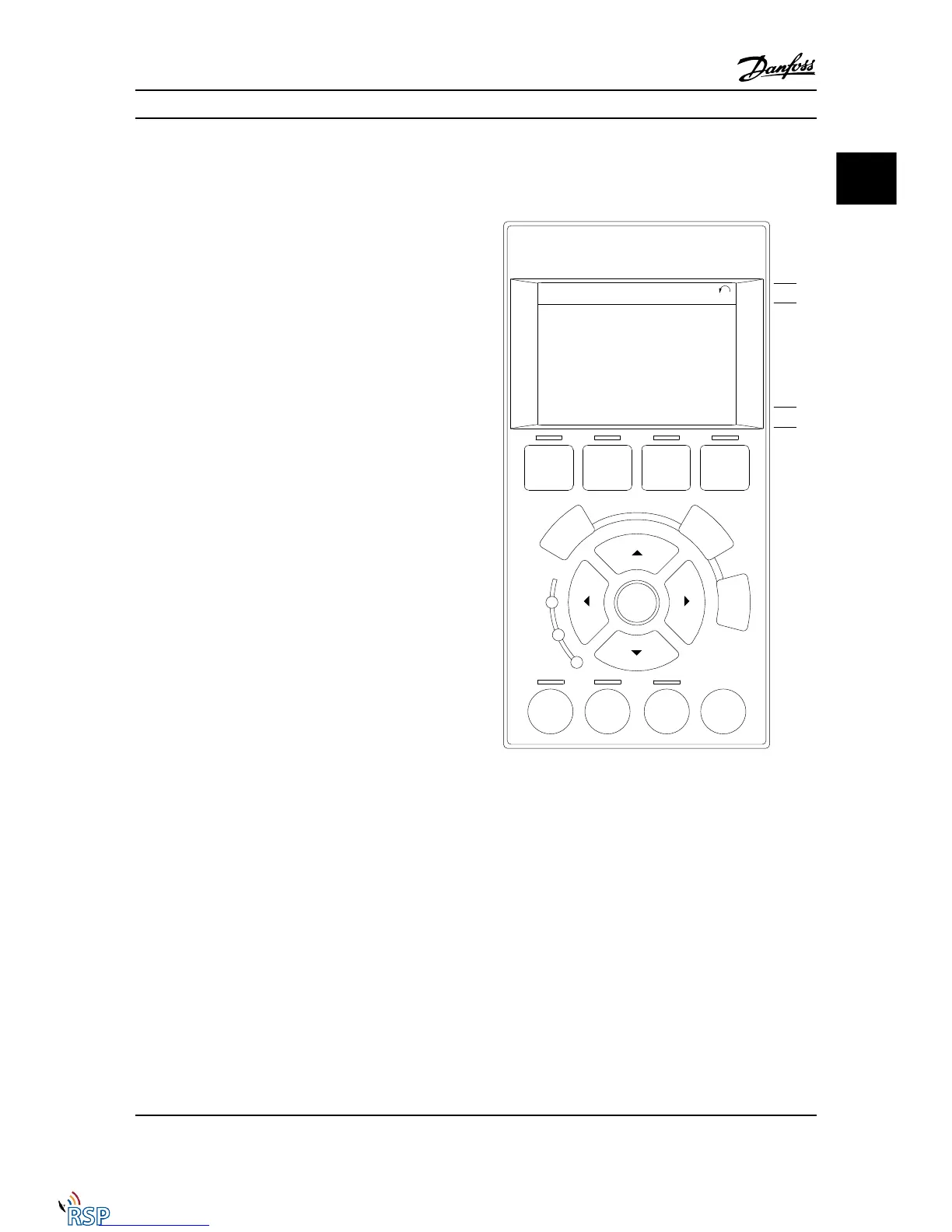
The control panel is divided into four functional groups.
1. Graphical display with Status lines.
2. Menu keys and LEDs - changing parameters and
switching between display functions.
3. Navigation keys and LEDs (LEDs).
4. Operation keys and LEDs.
All data is displayed in a graphical LCP display, which can
show up to five items of operating data while displaying
[Status].
Display lines
a. Status line: Status messages displaying icons and
graphic.
b. Line 1-2: Operator data lines displaying data
defined or chosen by the user. By pressing the
[Status] key, up to one extra line can be added.
c. Status line: Status messages displaying text.
2.1.2
The LCD Display
The LCD display has back lighting and a total of 6 alpha-
numeric lines. The display lines show the direction of
rotation (arrow), the chosen Set-up as well as the
programming Set-up. The display is divided into three
sections.
Top section shows up to two measurements in normal
operating status.
The top line in the Middle section shows up to five
measurements with related unit, regardless of status
(except in the case of alarm/warning).
The bottom section always shows the state of the
Adjustable frequency drive in status mode.
How to Program FC 300 Programming Guide
MG33MD22 - VLT
®
is a registered Danfoss trademark 2-1
2 2

 Loading...


