3.3.10.5 Klixon
The Klixon type thermal circuit breaker uses a KLIXON
®
metal dish. At a predetermined overload, the heat caused
by the current through the disc causes a trip.
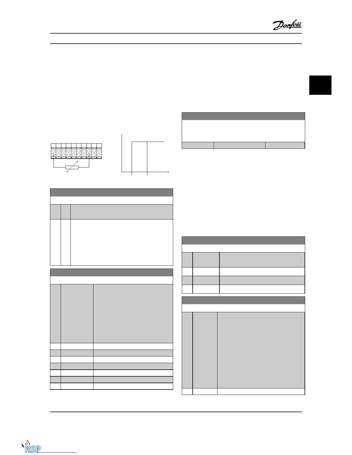
Using a digital input and 24 V as power supply:
Example: The Adjustable frequency drive trips when the
motor temperature is too high
Parameter set-up:
Set 1-90 Motor Thermal Protection to Thermistor Trip [2]
Set 1-93 Thermistor Source to Digital Input [6]
1-91 Motor External Fan
Option: Function:
[0] * No No external fan is required, i.e., the motor is derated
at low speed.
[1] Yes Applies an external motor fan (external ventilation), so
that no derating of the motor is required at low
speed. The upper curve in graph above (fout = 1 x
fM,N) is followed if the motor current is lower than
nominal motor current (see 1-24 Motor Current). If the
motor current exceeds nominal current, the operation
time still decreases as if no fan were installed.
1-93 Thermistor Source
Option: Function:
Select the input to which the thermistor
(PTC sensor) should be connected. An
analog input option [1] or [2] cannot be
selected if the analog input is already in
use as a reference source (selected in
3-15 Reference 1 Source, 3-16 Reference 2
Source or 3-17 Reference 3 Source ).
When using MCB 112, choice [0] None
must always be selected.
[0] * None
[1] Analog input 53
[2] Analog input 54
[3] Digital input 18
[4] Digital input 19
[5] Digital input 32
[6] Digital input 33
NOTE!
This parameter cannot be adjusted while the motor is
running.
NOTE!
Digital input should be set to [0] PNP - Active at 24V in
5-00 Digital I/O Mode.
1-94 ATEX ETR cur.lim. speed reduction
FC 302 only.
Only visible if 1-90 Motor Thermal Protection is set to [20].
Range: Function:
0.0 %* [0.0 - 100.0 %]
The reaction for operating in Ex-e current limit must be
configured.
0%: The Adjustable frequency drive does not change
anything besides issuing warning 163 ATEX ETR
cur.lim.warning.
>0%: The Adjustable frequency drive issuing warning 163
and reduces motor speed following ramp 2 (parameter
group 3-5*).
Example:
Actual reference = 50 RPM
1-94 ATEX ETR cur.lim. speed reduction = 20%
Resulting reference = 40 RPM
1-95 KTY Sensor Type
Option: Function:
Select the used type of KTY sensor. FC 302
only.
[0] * KTY Sensor 1 1kΩ at 212° F [100° C]
[1] KTY Sensor 2 1kΩ at 77 °F [25 °C]
[2] KTY Sensor 3 2kΩ at 77 °F [25 °C]
1-96 KTY Thermistor Resource
Option: Function:
Selecting analog input terminal 54 to be used
as KTY sensor input. Terminal 54 cannot be
selected as KTY source if otherwise used as
reference (see 3-15 Reference Resource 1 to
3-17 Reference Resource 3).
FC 302 only.
NOTE!
Connection of KTY sensor between term.
54 and 55 (GND). See picture in section
KTY Sensor Connection.
[0] * None
Parameter Descriptions FC 300 Programming Guide
MG33MD22 - VLT
®
is a registered Danfoss trademark 3-27
3
3

 Loading...


