2.1.15
Value, Step-by-Step
Certain parameters can be changed step by step or
infinitely varying. This applies to 1-20 Motor Power [kW],
1-22 Motor Voltage and 1-23 Motor Frequency.
The parameters are changed both as a group of numeric
data values and as numeric data values infinitely varying.
2.1.16
Readout and Programming of
Indexed Parameters
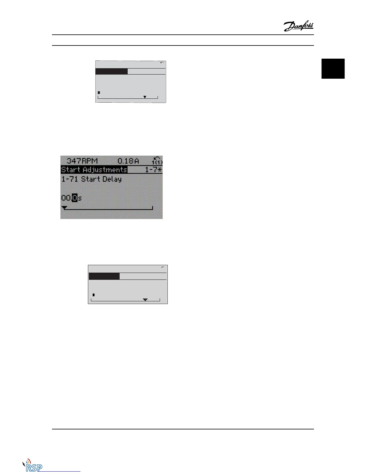
Parameters are indexed when placed in a rolling stack.
15-30 Fault Log: Error Code
to 15-32 Alarm Log: Time contain
a fault log which can be read out. Choose a parameter,
press [OK], and use the [
▲
] [
▼
] navigation keys to scroll
through the value log.
Use 3-10 Preset Reference as another example:
Choose the parameter, press [OK], and use the [
▲
] [
▼
]
navigation keys to scroll through the indexed values. To
change the parameter value, select the indexed value and
press [OK]. Change the value by using the [
▲
] [
▼
] keys.
Press [OK] to accept the new setting. Press [CANCEL] to
abort. Press [Back] to leave the parameter.
2.1.17
How to Program on the Numerical
Local Control Panel
The following instructions are valid for the Numerical LCP
(LCP 101).
The control panel is divided into four functional groups:
1. Numerical display.
2. Menu keys and LEDs - changing parameters and
switching between display functions.
3. Navigation keys and LEDs (LEDs).
4. Operation keys and LEDs.
Display line: Status messages displaying icons and numeric
value.
LEDs
•
Green LED/On: Indicates if control section is on.
•
Yellow LED/Wrn.: Indicates a warning.
•
Flashing red LED/Alarm: Indicates an alarm.
How to Program FC 300 Programming Guide
MG33MD22 - VLT
®
is a registered Danfoss trademark 2-9
2 2

 Loading...


