1-58 Flystart Test Pulses Current
Range: Function:
active when 1-73 Flying Start is enabled. This
parameter is only available in VVC
plus
.
1-59 Flystart Test Pulses Frequency
Range: Function:
200 %* [0 - 500
%]
Control the percentage of the frequency for
the pulses used to detect the motor
direction. Increasing this value will reduce
the generated torque. 100% means 2 times
the slip frequency. The parameter is active
when 1-73 Flying Start is enabled. This
parameter is only available in VVC
plus
.
3.3.6 1-6* Load Depend. Setting
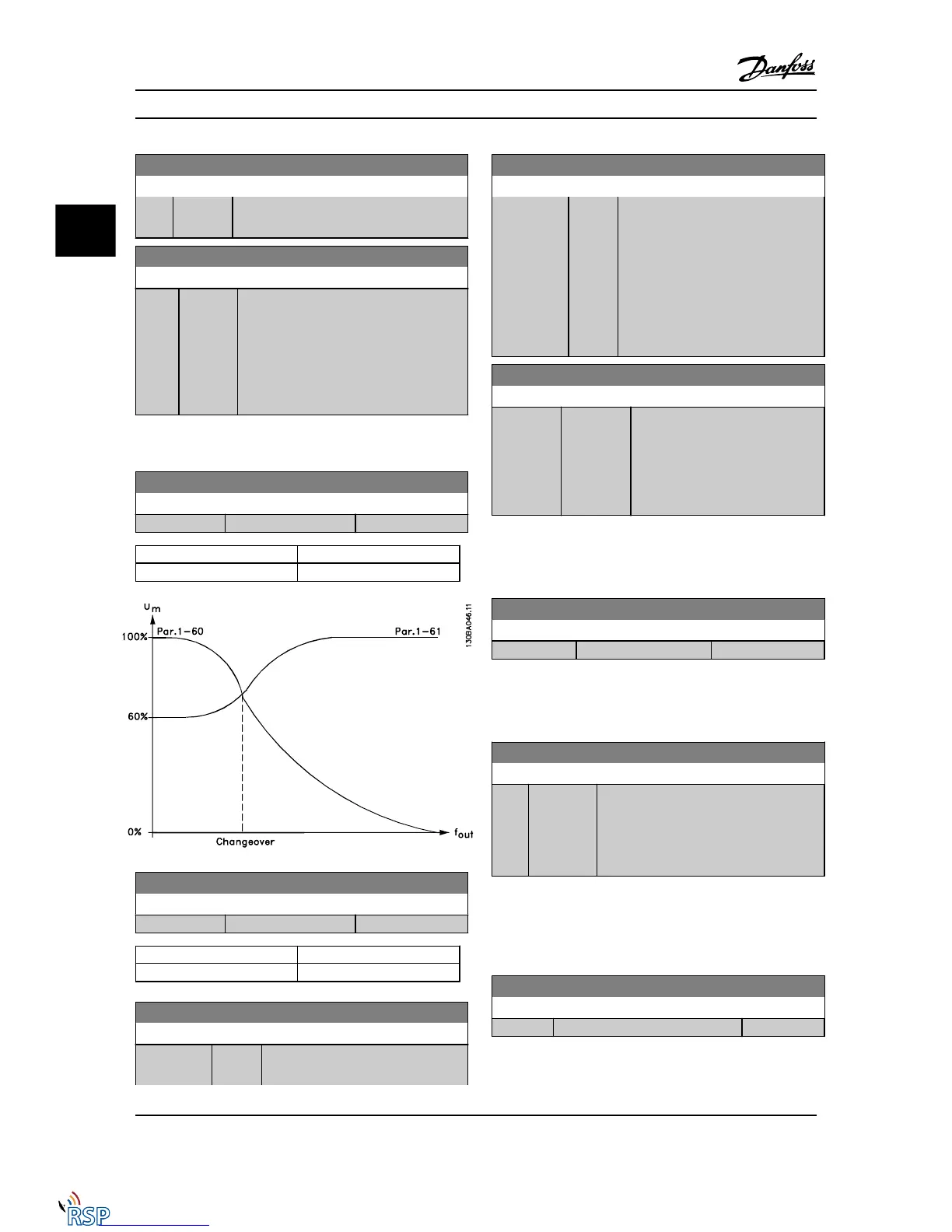
1-60 Low Speed Load Compensation
Range: Function:
100 %* [0 - 300 %]
Motor size Change-over
0.34–10 hp [0.25–7.5 kW] < 10Hz
1-61 High Speed Load Compensation
Range: Function:
100 %* [0 - 300 %]
Motor size Change-over
0.34–10 hp [0.25–7.5 kW] > 10Hz
1-62 Slip Compensation
Range: Function:
Application
dependent*
[-500 -
500 %]
Enter the % value for slip compensation
to compensate for tolerances in the
1-62 Slip Compensation
Range: Function:
value of n
M,N
. Slip compensation is
calculated automatically, i.e., on the
basis of the rated motor speed n
M,N
.
This function is not active when
1-00 Configuration Mode is set to Speed
closed-loop [1] or Torque [2] Torque
control with speed feedback or when
1-01 Motor Control Principle is set to U/f
[0] special motor mode.
1-63 Slip Compensation Time Constant
Range: Function:
Size related* [0.05 - 5.00
s]
Enter the slip compensation reaction
speed. A high value results in slow
reaction, and a low value results in
quick reaction. If low-frequency
resonance problems arise, use a
longer time setting.
NOTE!
1-63 Slip Compensation Time Constant will not have effect
when 1-10 Motor Construction = [1] PM, non-salient SPM.
1-64 Resonance Dampening
Range: Function:
100 %* [0 - 500 %]
NOTE!
1-64 Resonance Dampening will not have effect when
1-10 Motor Construction = [1] PM, non-salient SPM.
1-65 Resonance Dampening Time Constant
Range: Function:
5 ms* [5 - 50 ms]
Set 1-64 Resonance Dampening and
1-65 Resonance Dampening Time Constant to
help eliminate high-frequency resonance
problems. Enter the time constant that
provides the best dampening.
NOTE!
1-65 Resonance Dampening Time Constant will not have
effect when 1-10 Motor Construction = [1] PM, non-salient
SPM.
1-66 Min. Current at Low Speed
Range: Function:
100 %* [Application dependant]
Parameter Descriptions FC 300 Programming Guide
3-20 MG33MD22 - VLT
®
is a registered Danfoss trademark
3
3

 Loading...


