3-15 Reference Resource 1
Option: Function:
Select the reference input to be used
for the first reference signal.
3-15 Reference Resource 1,
3-16 Reference Resource 2 and
3-17 Reference Resource 3 define up to
three different reference signals. The
sum of these reference signals
defines the actual reference.
[0] No function
[1] * Analog input 53
[2] Analog input 54
[7] Frequency input 29
[8] Frequency input 33
[11] Local bus reference
[20] Digital pot.meter
[21] Analog input X30-11 (General Purpose I/O Option Module)
[22] Analog input X30-12 (General Purpose I/O Option Module)
[29] Analog Input X48/2
3-16 Reference Resource 2
Option: Function:
Select the reference input to be
used for the second reference
signal. 3-15 Reference Resource 1,
3-16 Reference Resource 2 and
3-17 Reference Resource 3 define up
to three different reference signals.
The sum of these reference signals
defines the actual reference.
3-16 Reference Resource 2
Option: Function:
[0] No function
[1] Analog input 53
[2] Analog input 54
[7] Frequency input 29
[8] Frequency input 33
[11] Local bus reference
[20] * Digital pot.meter
[21] Analog input X30-11
[22] Analog input X30-12
[29] Analog Input X48/2
3-17 Reference Resource 3
Option: Function:
Select the reference input to be
used for the third reference signal.
3-15 Reference Resource 1,
3-16 Reference Resource 2 and
3-17 Reference Resource 3 define up
to three different reference signals.
The sum of these reference signals
defines the actual reference.
[0] No function
[1] Analog input 53
[2] Analog input 54
[7] Frequency input 29
[8] Frequency input 33
[11] * Local bus reference
[20] Digital pot.meter
[21] Analog input X30-11
[22] Analog input X30-12
[29] Analog Input X48/2
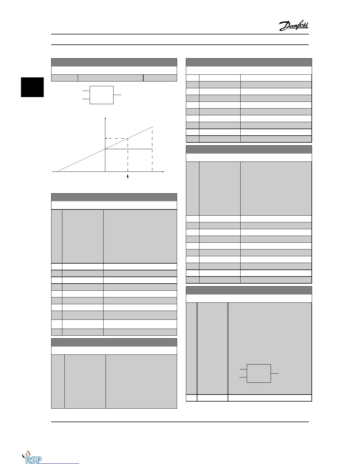
3-18 Relative Scaling Reference Resource
Option: Function:
Select a variable value to be added to the
fixed value (defined in 3-14 Preset Relative
Reference). The sum of the fixed and
variable values (labeled Y in the figure
below) is multiplied by the actual reference
(labeled X in the figure below). The result
is then added to the actual reference (X
+X*Y/100) to give the resulting actual
reference.

 Loading...


