2-20 Release Brake Current
Range: Function:
Application
dependent*
[Application
dependant]
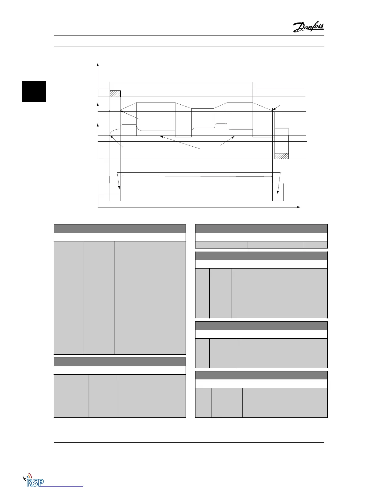
Set the motor current for release
of the mechanical brake, when a
start condition is present. The
default value is the maximum
current the inverter can provide
for the particular power size. The
upper limit is specified in
16-37 Inv. Max. Current.
NOTE!
When Mechanical brake
control output is selected but
no mechanical brake is
connected, the function will
not work by default setting
due to too low motor current.
2-21 Activate Brake Speed [RPM]
Range: Function:
Application
dependent*
[0 - 30000
RPM]
Set the motor speed for
activation of the mechanical
brake, when a stop condition is
present. The upper speed limit is
specified in 4-53 Warning Speed
High.
2-22 Activate Brake Speed [Hz]
Range: Function:
Application dependent* [Application dependant]
2-23 Activate Brake Delay
Range: Function:
0.0 s* [0.0 -
5.0 s]
Enter the brake delay time of the coast after
ramp-down time. The shaft is held at zero
speed with full holding torque. Ensure that the
mechanical brake has locked the load before
the motor enters coast mode. See the
Mechanical Brake Control section in the Design
Guide.
2-24 Stop Delay
Range: Function:
0.0 s* [0.0 - 5.0 s] Set the time interval from the moment
when the motor is stopped until the brake
closes. This parameter is a part of the
stopping function.
2-25 Brake Release Time
Range: Function:
0.20 s* [0.00 - 5.00
s]
This value defines the time it takes for
the mechanical brake to open. This
parameter must act as a timeout when
brake feedback is activated.
Parameter Descriptions FC 300 Programming Guide
3-32 MG33MD22 - VLT
®
is a registered Danfoss trademark
3
3

 Loading...


