The “protection mode” can be disabled by setting
14-26 Trip Delay at Inverter Fault to zero which means that
the Adjustable frequency drive will trip immediately if one
of the hardware limits is exceeded.
NOTE!
It is recommended to disable protection mode in hoisting
applications (14-26 Trip Delay at Inverter Fault = 0)
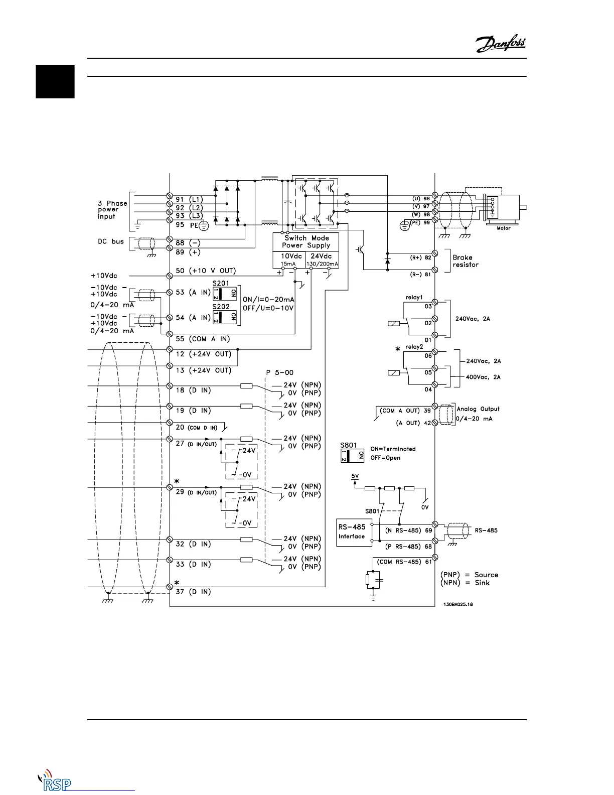
1.1.5 Electrical Wiring - Control Cables
Figure 1.1 Diagram showing all electrical terminals without options.
Terminal 37 is the input to be used for Safe Stop. For instructions on Safe Stop installation please, refer to the section Safe Stop Instal-
lation of the Design Guide.
* Terminal 37 is not included in FC 301 (Except FC 301 A1, which includes Safe Stop).
Terminal 29 and Relay 2, are not included in FC 301.
Introduction FC 300 Programming Guide
1-6 MG33MD22 - VLT
®
is a registered Danfoss trademark
11
Remote Site Products - 1-888-532-2706 - www.remotesiteproducts.com
http://www.remotesiteproducts.com/p-20872-Danfoss-131H4490-VLT-Automation-VT-Drive-VFD-FC302-460V-25-HP.aspx

 Loading...


