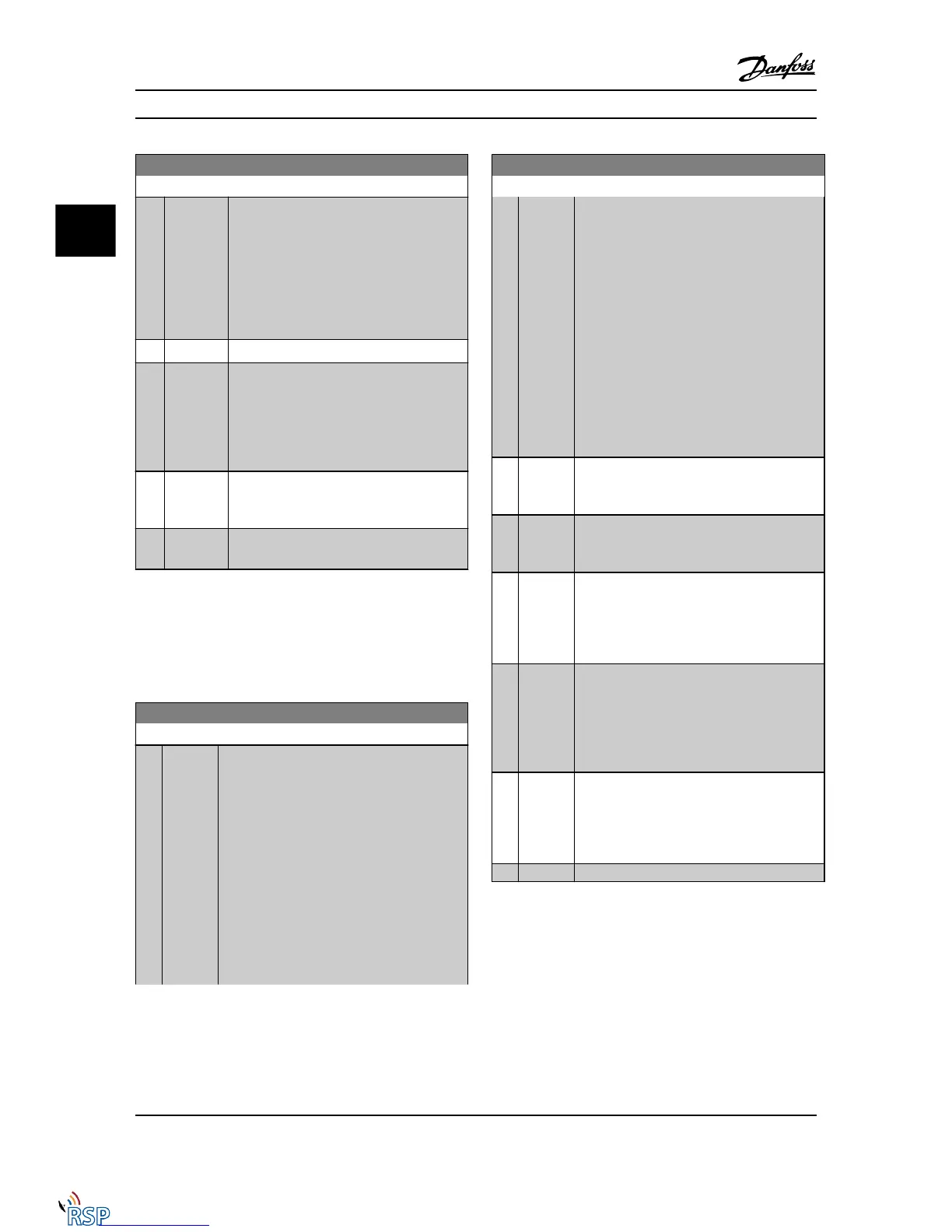
2-13 Brake Power Monitoring
Option: Function:
This parameter is only active in adjustable
frequency drives with an integral dynamic
brake.
This parameter enables monitoring of the
power to the brake resistor. The power is
calculated on the basis of the resistance
(2-11 Brake Resistor (ohm)), the DC-link voltage,
and the resistor duty time.
[0] * Off No braking energy monitoring required.
[1] Warning Activates a warning on the display when the
power transmitted over 120 s exceeds 100% of
the monitoring limit (2-12 Brake Power Limit
(kW)).
The warning disappears when the transmitted
power falls below 80% of the monitoring limit.
[2] Trip Trips Adjustable frequency drive and displays
an alarm when the calculated power exceeds
100% of the monitoring limit.
[3] Warning
and trip
Activates both of the above, including
warning, trip and alarm.
If power monitoring is set to Off [0] or Warning [1], the
brake function remains active, even if the monitoring limit
is exceeded. This may lead to thermal overload of the
resistor. It is also possible to generate a warning via a
relay/digital output. The measuring accuracy of the power
monitoring depends on the accuracy of the resistance of
the resistor (better than ± 20%).
2-15 Brake Check
Option: Function:
Select type of test and monitoring function to
check the connection to the brake resistor, or
whether a brake resistor is present, and then
display a warning or an alarm in the event of a
fault.
NOTE!
The brake resistor disconnection function is
tested during power-up. However, the
brake IGBT test is performed when there is
no braking. A warning or trip disconnects
the brake function.
The testing sequence is as follows:
2-15 Brake Check
Option: Function:
1. The DC link ripple amplitude is
measured for 300 ms without braking.
2. The DC link ripple amplitude is
measured for 300 ms with the brake
turned on.
3. If the DC link ripple amplitude while
braking is lower than the DC link ripple
amplitude before braking + 1%: Brake
check has failed by returning a warning
or alarm.
4. If the DC link ripple amplitude while
braking is higher than the DC link
ripple amplitude before braking + 1%:
Brake check is OK.
[0]
*
Off Monitors brake resistor and brake IGBT for a
short-circuit during operation. If a short-circuit
occurs, warning 25 appears.
[1] Warning Monitors brake resistor and brake IGBT for a
short-circuit, and runs a test for brake resistor
disconnection during power-up.
[2] Trip Monitors for a short-circuit or disconnection of
the brake resistor, or a short-circuit of the brake
IGBT. If a fault occurs, the Adjustable frequency
drive cuts out while displaying an alarm (trip
locked).
[3] Stop and
trip
Monitors for a short-circuit or disconnection of
the brake resistor, or a short-circuit of the brake
IGBT. If a fault occurs, the Adjustable frequency
drive ramps down to coast and then trips. A trip
lock alarm is displayed (e.g., warning 25, 27 or
28).
[4] AC brake Monitors for a short-circuit or disconnection of
the brake resistor, or a short-circuit of the brake
IGBT. If a fault occurs, the Adjustable frequency
drive performs a controlled ramp-down. This
option is available for FC 302 only.
[5] Trip Lock
NOTE!
Remove a warning arising in connection with Off [0] or
Warning [1] by cycling the line power supply. The fault
must be corrected first. For Off [0] or Warning [1], the
Adjustable frequency drive keeps running even if a fault is
located.
This parameter is only active in adjustable frequency drives
with an integral dynamic brake.
Parameter Descriptions FC 300 Programming Guide
3-30 MG33MD22 - VLT
®
is a registered Danfoss trademark
3
3

 Loading...


