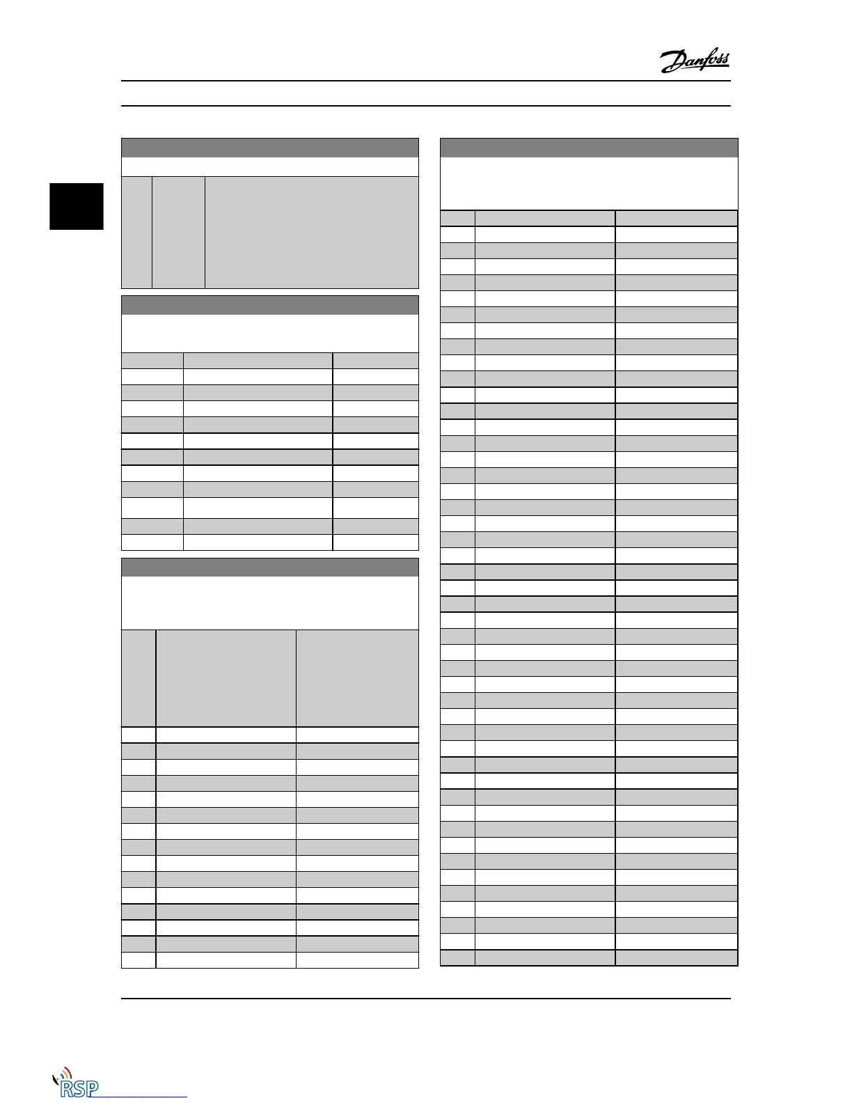
9-18 Node Address
Range: Function:
126 * [ 0 -
126. ]
Enter the station address in this parameter or
alternatively in the hardware switch. In order
to adjust the station address in 9-18 Node
Address, the hardware switch must be set to
126 or 127 (i.e. all switches set to ‘on’).
Otherwise this parameter will display the
actual setting of the switch.
9-22 Telegram Selection
Displays the Profibus telegram configuration.
Option: Function:
[1] Standard telegram 1
[100] * None
[101] PPO 1
[102] PPO 2
[103] PPO 3
[104] PPO 4
[105] PPO 5
[106] PPO 6
[107] PPO 7
[108] * PPO 8 Read only.
[200] Custom telegram 1
[202] Custom telegram 3
9-23 Parameters for Signals
Array [1000]
Read only
Option: Function:
This parameter contains a
list of signals available for
selection in 9-15 PCD
Write Configuration and
9-16 PCD Read Configu-
ration.
[0] * None
[15] Readout: actual setup
[302] Minimum Reference
[303] Maximum Reference
[312] Catch up/slow Down Value
[341] Ramp 1 Ramp up Time
[342] Ramp 1 Ramp Down Time
[351] Ramp 2 Ramp up Time
[352] Ramp 2 Ramp down Time
[380] Jog Ramp Time
[381] Quick Stop Ramp Time
[411] Motor Speed Low Limit [RPM]
[412] Motor Speed Low Limit [Hz]
[413] Motor Speed High Limit [RPM]
[414] Motor Speed High Limit [Hz]
9-23 Parameters for Signals
Array [1000]
Read only
Option: Function:
[416] Torque Limit Motor Mode
[417] Torque Limit Generator Mode
[590] Digital & Relay Bus Control
[593] Pulse Out #27 Bus Control
[595] Pulse Out #29 Bus Control
[597] Pulse Out #X30/6 Bus Control
[653] Term 42 Output Bus Ctrl
[663] Terminal X30/8 Bus Control
[673] Terminal X45/1 Bus Control
[683] Terminal X45/3 Bus Control
[748] PCD Feed Forward
[890] Bus Jog 1 Speed
[891] Bus Jog 2 Speed
[1472] Legacy Alarm Word
[1473] Legacy Warning Word
[1474] Leg. Ext. Status Word
[1500] Operating Hours
[1501] Running Hours
[1502] kWh Counter
[1600] Control Word
[1601] Reference [Unit]
[1602] Reference %
[1603] Status Word
[1605] Main Actual Value [%]
[1609] Custom Readout
[1610] Power [kW]
[1611] Power [hp]
[1612] Motor Voltage
[1613] Frequency
[1614] Motor Current
[1615] Frequency [%]
[1616] Torque [Nm]
[1617] Speed [RPM]
[1618] Motor Thermal
[1619] KTY sensor temperature
[1620] Motor Angle
[1621] Torque [%] High Res.
[1622] Torque [%]
[1625] Torque [Nm] High
[1630] DC Link Voltage
[1632] Brake Energy /s
[1633] Brake Energy /2 min
[1634] Heatsink Temp.
[1635] Inverter Thermal
[1638] SL Controller State
[1639] Control Card Temp.
[1650] External Reference
Parameter Descriptions FC 300 Programming Guide
3-96 MG33MD22 - VLT
®
is a registered Danfoss trademark
3
3

 Loading...


