1-96 KTY Thermistor Resource
Option: Function:
[2] Analog
input 54
1-97 KTY Threshold level
Range: Function:
80 C* [-40 - 140 C]
1-98 ATEX ETR interpol. points freq.
FC 302 only.
Only visible if 1-90 Motor Thermal Protection is set to [20].
Range: Function:
Application
dependent*
[Application
dependant]
Definition of
thermal limitation
curve.
Enter the four frequency points [Hz] from the motor
nameplate into this array. Together with 1-99 ATEX ETR
interpol points current, these make up a table (f [Hz],I [%]).
NOTE!
All frequency/current limit points from the motor
nameplate or motor data sheet must be programmed.
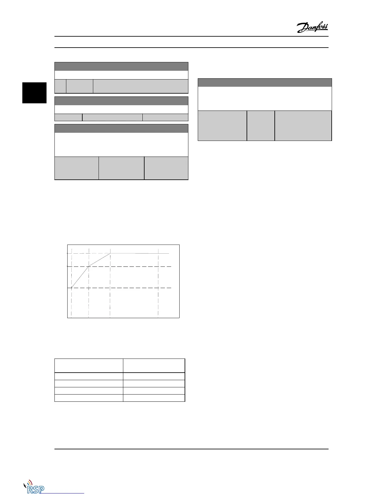
Figure 3.7 Example of ATEX ETR thermal limitation curve.
x-axis: f
m
[Hz]
y-axis: I
m
/I
m,n
x 100 [%]
1-98 ATEX ETR interpol. points freq. 1-99 ATEX ETR interpol points
current
[0] = 5 Hz [0] = 40%
[1] = 15 Hz [1] = 80%
[2] = 25 Hz [2] = 100%
[3] = 50 Hz [3] = 100%
All operating points underneath the curve are allowed
continuously. Above the line, however, only for a limited
time calculated as a function of the overload. In the event
of a machine current greater than 1.5 times the rated
current, shut down is immediate.
1-99 ATEX ETR interpol points current
FC 302 only.
Only visible if 1-90 Motor Thermal Protection is set to [20] or [21].
Range: Function:
Application
dependent*
[0 - 100 %] Definition of thermal
limitation curve. For
example, see 1-98 ATEX
ETR interpol. points freq.
Use the four current points [A] from the motor nameplate.
Calculate the values as percentage of nominal motor
current, I
m
/I
m,n
x 100 [%], and enter into this array.
Together with 1-98 ATEX ETR interpol. points freq., these
make up a table (f [Hz],I [%]).
NOTE!
All frequency/current limit points from the motor
nameplate or motor data sheet must be programmed.
Parameter Descriptions FC 300 Programming Guide
3-28 MG33MD22 - VLT
®
is a registered Danfoss trademark
3
3

 Loading...


