3.15.2 14-1* Mains On/Off
Parameters for configuring line failure monitoring and
handling. If a line failure appears, the Adjustable frequency
drive will try to continue in a controlled way until the
power in the DC link has been exhausted.
14-10 Mains Failure
Option: Function:
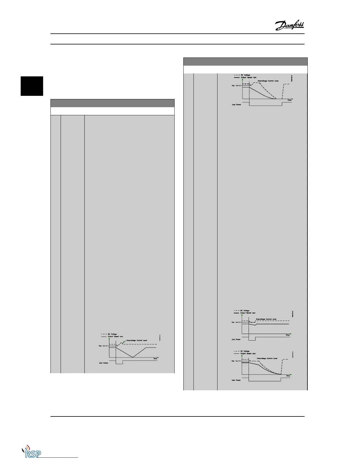
14-10 Mains Failure is typically used where very
short line power interruptions (voltage dips)
are present. At 100% load and a short voltage
interruption, the DC voltage on the main
capacitors drops quickly. For larger drives it
only takes a few milliseconds before the DC
level is down to about 373 V DC and the main
IGBT cuts off and looses the control over the
motor. When the mains is restored, and the
IGBT starts again, the output frequency and
voltage vector does not correspond to the
speed/frequency of the motor, and the result is
normally an overvoltage or overcurrent, mostly
resulting in a trip lock. 14-10 Mains Failure can
be programmed to avoid this situation.
Select the function to which the Adjustable
frequency drive must act when the threshold
in 14-11 Mains Voltage at Mains Fault has been
reached.
14-10 Mains Failure cannot be changed while
motor is running.
Controlled ramp-down:
The Adjustable frequency drive will perform a
controlled ramp-down. If 2-10 Brake Function is
Off [0] or AC brake [2], the ramp will follow the
Overvoltage Ramping. If 2-10 Brake Function is
[1] Resistor Brake, the ramp will follow the
setting in 3-81 Quick Stop Ramp Time.
Controlled ramp-down [1]:
After power-up, the Adjustable frequency drive
is ready for start. Controlled ramp-down and
trip [2]: After power-up, the Adjustable
frequency drive needs a reset for starting.
14-10 Mains Failure
Option: Function:
1. The power is back before the energy
from DC / moment of inertia from
load is too low. The Adjustable
frequency drive will perform a
controlled ramp-down when
14-11 Mains Voltage at Mains Fault
level has been reached.
2. The Adjustable frequency drive will
perform a controlled ramp-down as
long as energy in the DC link is
present. After this point, the motor
will be coasted.
Kinetic backup:
The Adjustable frequency drive will perform a
kinetic backup. If 2-10 Brake Function is Off [0]
or AC brake [2], the ramp will follow the
overvoltage ramping. If 2-10 Brake Function is
[1] Resistor Brake, the ramp will follow the
setting in 3-81 Quick Stop Ramp Time.
Kinetic Backup [4]: The Adjustable frequency
drive will keep on running as long as there is
energy in the system due to the moment of
inertia produced by the load.
Kinetic Backup [5]: The Adjustable frequency
drive will ride through on speed as long as the
energy is present from moment of inertia from
the load. If the DC voltage goes below
14-11 Mains Voltage at Mains Fault, the
Adjustable frequency drive will perform a trip.
Parameter Descriptions FC 300 Programming Guide
3-128 MG33MD22 - VLT
®
is a registered Danfoss trademark
3
3

 Loading...


