3.12 Parameters: 10-** DeviceNet CAN
Fieldbus
3.12.1 10-0* Common Settings
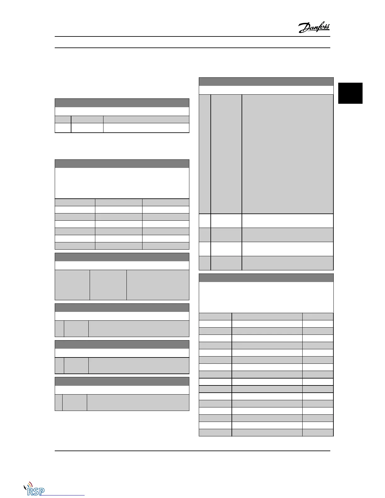
10-00 CAN Protocol
Option: Function:
[0] CANopen
[1] * DeviceNet View the active CAN protocol.
NOTE!
The options depend on installed option.
10-01 Baud Rate Select
Select the serial communication bus transmission speed. The
selection must correspond to the transmission speed of the
master and the other serial communication bus nodes.
Option: Function:
[16] 10 Kbps
[17] 20 Kbps
[18] 50 Kbps
[19] 100 Kbps
[20] * 125 Kbps
[21] 250 Kbps
[22] 500 Kbps
10-02 MAC ID
Range: Function:
Application
dependent*
[Application
dependant]
Selection of station address.
Every station connected to
the same network must have
an unambiguous address.
10-05 Readout Transmit Error Counter
Range: Function:
0 * [0 - 255 ] View the number of CAN control transmission
errors since the last power-up.
10-06 Readout Receive Error Counter
Range: Function:
0 * [0 - 255 ] View the number of CAN control receipt errors
since the last power-up.
10-07 Readout Bus Off Counter
Range: Function:
0* [0 - 255 ] View the number of Bus Off events since the last
power-up.
3.12.2 10-1* DeviceNet
10-10 Process Data Type Selection
Option: Function:
Select the Instance (message) for data
transmission. The instances available are
dependent upon the setting of 8-10 Control
Profile.
When 8-10 Control Profile is set to [0] FC
profile, 10-10 Process Data Type Selection
options [0] and [1] are available.
When 8-10 Control Profile is set to [5] ODVA,
10-10 Process Data Type Selection options [2]
and [3] are available.
Instances 100/150 and 101/151 are Danfoss-
specific. Instances 20/70 and 21/71 are
ODVA-specific AC Drive profiles.
For guidelines in message selection, please
refer to the DeviceNet Instruction Manual.
Note that a change to this parameter will
be executed immediately.
[0] * INSTANCE
100/150
[1] INSTANCE
101/151
[2] INSTANCE
20/70
[3] INSTANCE
21/71
10-11 Process Data Config Write
Select the process write data for I/O assembly instances 101/151.
Elements [2] and [3] of this array can be selected. Elements [0]
and [1] of the array are fixed.
Option: Function:
[0] * None
[302] Minimum Reference
[303] Maximum Reference
[312] Catch up/slow Down Value
[341] Ramp 1 Ramp up Time
[342] Ramp 1 Ramp Down Time
[351] Ramp 2 Ramp up Time
[352] Ramp 2 Ramp down Time
[380] Jog Ramp Time
[381] Quick Stop Ramp Time
[411] Motor Speed Low Limit [RPM]
[412] Motor Speed Low Limit [Hz]
[413] Motor Speed High Limit [RPM]
[414] Motor Speed High Limit [Hz]
[416] Torque Limit Motor Mode
[417] Torque Limit Generator Mode
[590] Digital & Relay Bus Control
Parameter Descriptions FC 300 Programming Guide
MG33MD22 - VLT
®
is a registered Danfoss trademark 3-101
3
3

 Loading...


