5-57 Term. 33 Low Ref./Feedb. Value
Range: Function:
0.000 * [-999999.999 -
999999.999 ]
Enter the low reference value
[RPM] for the motor shaft speed.
This is also the low feedback
value, see also 5-52 Term. 29 Low
Ref./Feedb. Value.
5-58 Term. 33 High Ref./Feedb. Value
Range: Function:
Application
dependent*
[-999999.999 -
999999.999
ReferenceFeedbackUnit]
Enter the high
reference value [RPM]
for the motor shaft
speed. See also
5-53 Term. 29 High
Ref./Feedb. Value.
Application
dependent*
[-999999.999 -
999999.999
ReferenceFeedbackUnit]
5-59 Pulse Filter Time Constant #33
Range: Function:
100 ms* [1 - 1000
ms]
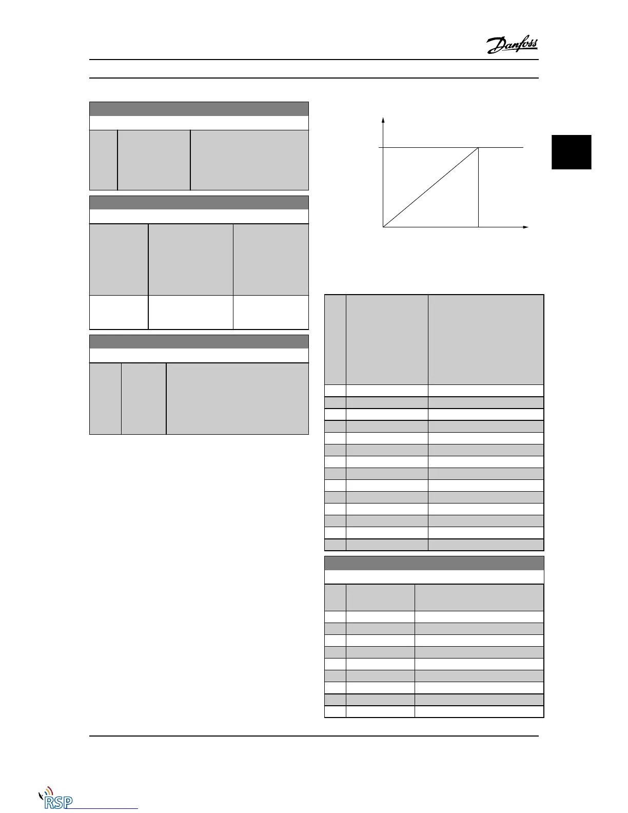
Enter the pulse filter time constant. The
low-pass filter reduces the influence on,
and dampens oscillations in, the feedback
signal from the control.
This is an advantage, if, for example, there
is a great amount of noise in the system.
NOTE!
This parameter cannot be adjusted while the motor is
running.
3.7.6 5-6* Pulse Outputs
These parameters are to configure pulse outputs with their
functions and scaling. Terminal 27 and 29 are allocated to
pulse output via 5-01 Terminal 27 Mode and 5-02 Terminal
29 Mode, respectively.
NOTE!
These parameters cannot be adjusted while the motor is
running.
Options for readout output variables:
Parameters for configuring the
scaling and output functions of
pulse outputs. The pulse outputs
are designated for terminals 27 or
29. Select terminal 27 output in
5-01 Terminal 27 Mode and
terminal 29 output in
5-02 Terminal 29 Mode.
[0] No operation
[45] Bus control
[48] Bus control timeout
[51] MCO controlled
[100] Output frequency
[101] Reference
[102] Feedback
[103] Motor current
[104] Torque relative to limit
[105] Torque relative to rated
[106] Power
[107] Speed
[108] Torque
[109] Max Out Freq
5-60 Terminal 27 Pulse Output Variable
Option: Function:
[0] * No operation Select the desired display output for
terminal 27.
[45] Bus ctrl.
[48] Bus ctrl., timeout
[51] MCO controlled
[100] Output frequency
[101] Reference
[102] Feedback
[103] Motor current
[104] Torque rel to limit
[105] Torq relate to rated
Parameter Descriptions FC 300 Programming Guide
MG33MD22 - VLT
®
is a registered Danfoss trademark 3-65
3
3
Remote Site Products - 1-888-532-2706 - www.remotesiteproducts.com
http://www.remotesiteproducts.com/p-20872-Danfoss-131H4490-VLT-Automation-VT-Drive-VFD-FC302-460V-25-HP.aspx

 Loading...


