Operating variable: Unit:
16-85 FC Port CTW 1
hex
16-86 FC Port REF 1
hex
16-90 Alarm Word
16-92 Warning Word
16-94 Ext. Status Word
Status screen I
This readout state is standard after start-up or initialization.
Use [INFO] to obtain information about the measurement
links to the displayed operating variables (1.1, 1.2, 1.3, 2
and 3).
See the operating variables shown in the screen below.
Status screen II
See the operating variables (1.1, 1.2, 1.3 and 2) shown in
the screen below.
In the example, Speed, Motor current, Motor power and
Frequency are selected as variables in the first and second.
2.1.6
Parameter Set-up
The Adjustable frequency drive can be used for practically
all assignments, which is why the number of parameters is
quite large. The Adjustable frequency drive offers a choice
between two programming modes - a Main Menu and a
Quick Menu mode.
The former provides access to all parameters. The latter
takes the user through a few parameters making it
possible to start operating the Adjustable frequency drive.
Regardless of the mode of programming, you can change
a parameter both in the main menu and quick menu
modes.
2.1.7
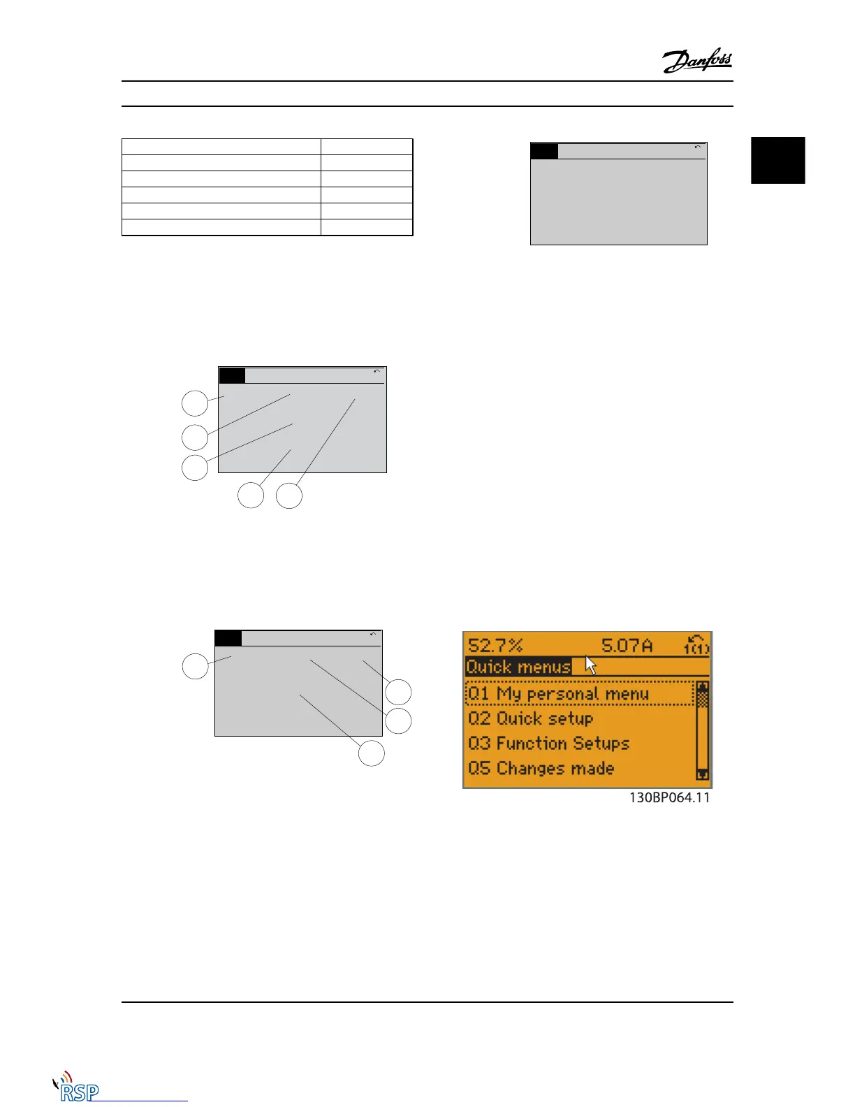
Quick Menu Key Functions
Pressing [Quick Menus] The list indicates the different
areas contained in the Quick menu.
Select My Personal Menu to display the chosen personal
parameters. These parameters are selected in 0-25 My
Personal Menu. Up to 20 different parameters can be
added in this menu.
Select Quick set-up to go through a limited amount of
parameters to get the motor running almost optimally. The
default setting for the other parameters considers the
desired control functions and the configuration of signal
inputs/outputs (control terminals).
Parameters are selected by using the arrow keys. The
parameters in the following table are accessible.
How to Program FC 300 Programming Guide
MG33MD22 - VLT
®
is a registered Danfoss trademark 2-5
2 2

 Loading...


