Data storage in LCP
1.
Go to 0-50 LCP Copy
2. Press the [OK] key
3. Select “All to LCP”
4. Press the [OK] key
All parameter settings are now stored in the LCP indicated
by the progress bar. When 100% is reached, press [OK].
NOTE!
Stop the motor before performing this operation.
Connect the LCP to another Adjustable frequency drive
and copy the parameter settings to this Adjustable
frequency drive as well.
Data transfer from LCP to Adjustable frequency drive
1.
Go to 0-50 LCP Copy
2. Press the [OK] key
3. Select “All from LCP”
4. Press the [OK] key
The parameter settings stored in the LCP are now
transferred to the Adjustable frequency drive indicated by
the progress bar. When 100% is reached, press [OK].
NOTE!
Stop the motor before performing this operation.
2.1.4 Display Mode
In normal operation, up to 5 different operating variables
can be indicated continuously in the middle section: 1.1,
1.2, and 1.3 as well as 2 and 3.
2.1.5
Display Mode - Selection of Readouts
It is possible to toggle between three status readout
screens by pressing the [Status] key.
Operating variables with different formatting are shown in
each status screen - see below.
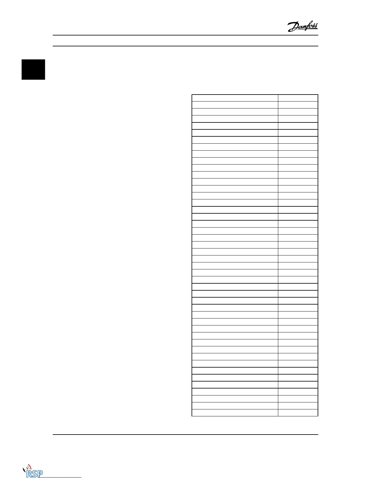
Table 2.1 shows the measurements you can link to each of
the operating variables. When Options are mounted,
additional measurements are available. Define the links via
0-20 Display Line 1.1 Small, 0-21 Display Line 1.2 Small,
0-22 Display Line 1.3 Small, 0-23 Display Line 2 Large, and
0-24 Display Line 3 Large.
Each readout parameter selected in 0-20 Display Line 1.1
Small to 0-24 Display Line 3 Large has its own scale and
digits after a possible decimal point. The larger the
numeric value for a parameter, the fewer digits displayed
after the decimal point.
Ex.: Current readout 5.25A; 15.2A 105A.
Operating variable: Unit:
16-00 Control Word
hex
16-01 Reference [Unit]
[unit]
16-02 Reference [%]
%
16-03 Status Word
hex
16-05 Main Actual Value [%]
%
16-10 Power [kW]
[kW]
16-11 Power [hp]
[HP]
16-12 Motor Voltage
[V]
16-13 Frequency
[Hz]
16-14 Motor Current
[A]
16-16 Torque [Nm]
Nm
16-17 Speed [RPM]
[RPM]
16-18 Motor Thermal
%
16-20 Motor Angle
16-30 DC Link Voltage
V
16-32 Brake Energy /s
kW
16-33 Brake Energy /2 min
kW
16-34 Heatsink Temp.
C
16-35 Inverter Thermal
%
16-36 Inv. Nom. Current
A
16-37 Inv. Max. Current
A
16-38 SL Controller State
16-39 Control Card Temp.
C
16-40 Logging Buffer Full
16-50 External Reference
16-51 Pulse Reference
16-52 Feedback [Unit]
[Unit]
16-53 Digi Pot Reference
16-60 Digital Input
bin
16-61 Terminal 53 Switch Setting
V
16-62 Analog Input 53
16-63 Terminal 54 Switch Setting
V
16-64 Analog Input 54
16-65 Analog Output 42 [mA]
[mA]
16-66 Digital Output [bin]
[bin]
16-67 Pulse Input #29 [Hz]
[Hz]
16-68 Freq. Input #33 [Hz]
[Hz]
16-69 Pulse Output #27 [Hz]
[Hz]
16-70 Pulse Output #29 [Hz]
[Hz]
16-71 Relay Output [bin]
16-72 Counter A
16-73 Counter B
16-80 Fieldbus CTW 1
hex
16-82 Fieldbus REF 1
hex
16-84 Comm. Option STW
hex
How to Program FC 300 Programming Guide
2-4 MG33MD22 - VLT
®
is a registered Danfoss trademark
22

 Loading...


