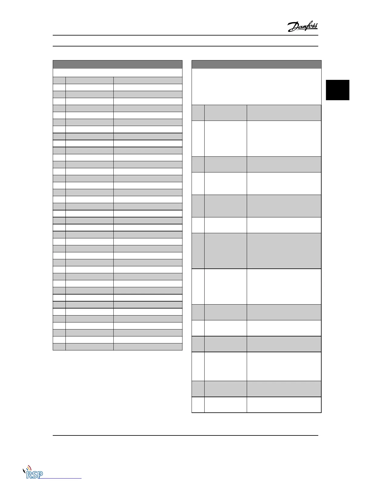
5-33 Term X30/7 Digi Out (MCB 101)
Option: Function:
[61] Comparator 1
[62] Comparator 2
[63] Comparator 3
[64] Comparator 4
[65] Comparator 5
[70] Logic rule 0
[71] Logic rule 1
[72] Logic rule 2
[73] Logic rule 3
[74] Logic rule 4
[75] Logic rule 5
[80] SL digital output A
[81] SL digital output B
[82] SL digital output C
[83] SL digital output D
[84] SL digital output E
[85] SL digital output F
[120] Local ref active
[121] Remote ref active
[122] No alarm
[123] Start command activ
[124] Running reverse
[125] Drive in hand mode
[126] Drive in auto mode
[151] ATEX ETR cur. alarm
[152] ATEX ETR freq. alarm
[153] ATEX ETR cur. warning
[154] ATEX ETR freq. warning
[189] External Fan Control
[190] Safe Function active
[191] Safe Opt. Reset req.
[192] RS Flipflop 0
[193] RS Flipflop 1
[194] RS Flipflop 2
[195] RS Flipflop 3
[196] RS Flipflop 4
[197] RS Flipflop 5
[198] RS Flipflop 6
[199] RS Flipflop 7
3.7.4 5-4* Relays
Parameters for configuring the timing and the output
functions for the relays.
5-40 Function Relay
Array [9]
(Relay 1 [0], Relay 2 [1], Relay 3 [2] (MCB 113), Relay 4 [3] (MCB
113), Relay 5 [4] (MCB 113), Relay 6 [5] (MCB 113), Relay 7 [6]
(MCB 105), Relay 8 [7] (MCB 105), Relay 9 [8] (MCB 105))
Option: Function:
[0] * No operation All digital and relay outputs are
default set to “No Operation”.
[1] Control ready The control card is ready. For
example, Feedback from a drive
where the control is supplied by an
external 24 V (MCB 107) and the
main power to drive is not detected.
[2] Drive ready Drive is ready to operate. Line power
and control supplies are OK.
[3] Drive rdy/rem ctrl The Adjustable frequency drive is
ready for operation and is in auto on
mode
[4] Enable / no warning Ready for operation. No start or stop
commands have been applied (start/
disable). No warnings are active.
[5] Running Motor is running, and shaft torque
present.
[6] Running / no
warning
Output speed is higher than the
speed set in 1-81 Min Speed for
Function at Stop [RPM] Min Speed for
Function at Stop [RPM]. The motor is
running and no warnings.
[7] Run in range/no
warn
Motor is running within the
programmed current and speed
ranges set in 4-50 Warning Current
Low and 4-53 Warning Speed High.
No warnings.
[8] Run on ref/no warn Motor runs at reference speed. No
warnings.
[9] Alarm An alarm activates the output. No
warnings
[10] Alarm or warning An alarm or a warning activates the
output.
[11] At torque limit
The torque limit set in 4-16 Torque
Limit Motor Mode or 4-17 Torque
Limit Generator Mode has been
exceeded.
[12] Out of current
range
The motor current is outside the
range set in 4-18 Current Limit.
[13] Below current, low
Motor current is lower than set in
4-50 Warning Current Low.
Parameter Descriptions FC 300 Programming Guide
MG33MD22 - VLT
®
is a registered Danfoss trademark 3-59
3
3

 Loading...


