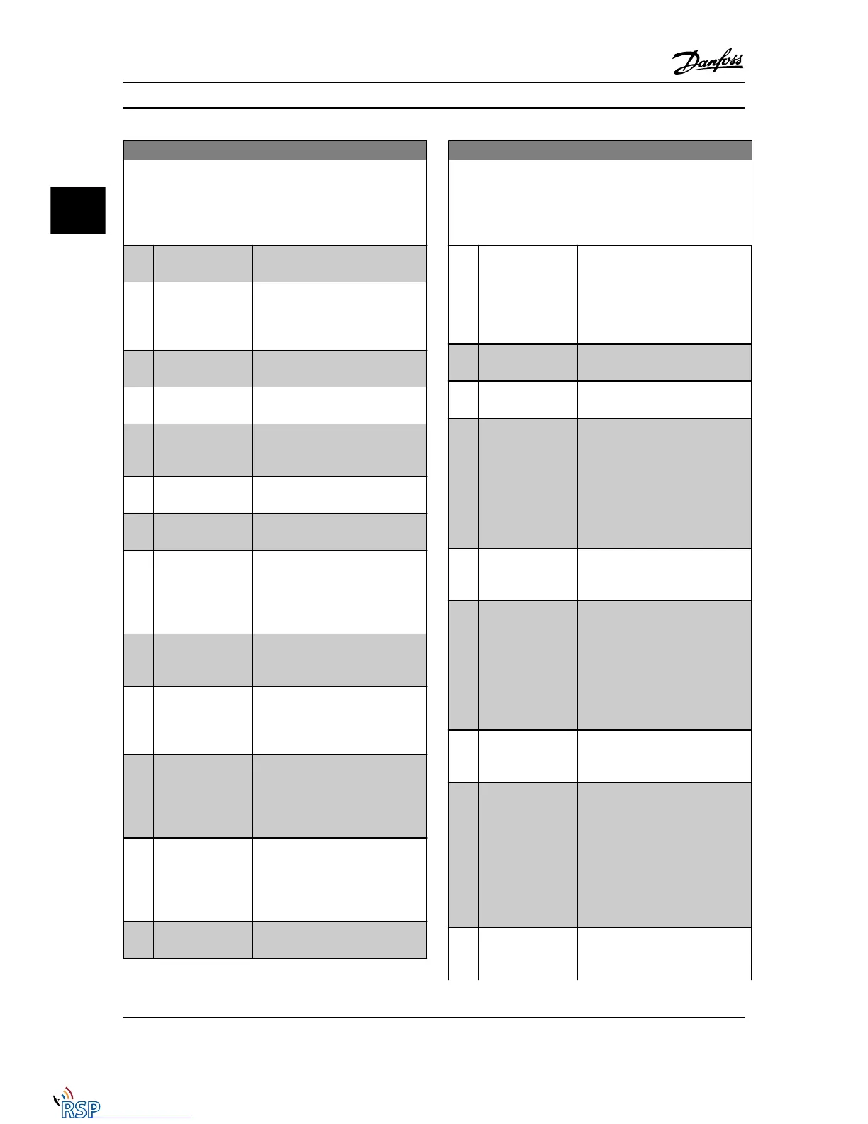
5-40 Function Relay
Array [9]
(Relay 1 [0], Relay 2 [1], Relay 3 [2] (MCB 113), Relay 4 [3] (MCB
113), Relay 5 [4] (MCB 113), Relay 6 [5] (MCB 113), Relay 7 [6]
(MCB 105), Relay 8 [7] (MCB 105), Relay 9 [8] (MCB 105))
Option: Function:
[14] Above current, high
Motor current is higher than set in
4-51 Warning Current High.
[15] Out of speed range Output speed/frequency is outside
the frequency ranges set in
4-52 Warning Speed Low and
4-53 Warning Speed High.
[16] Below speed, low Output speed is lower than the
setting in 4-52 Warning Speed Low
[17] Above speed, high Output speed is higher than the
setting in 4-53 Warning Speed High.
[18] Out of feedb. range
Feedback is outside the range set in
4-56 Warning Feedback Low and
4-57 Warning Feedback High.
[19] Below feedback, low
Feedback is below the limit set in
4-56 Warning Feedback Low.
[20] Above feedback,
high
Feedback is above the limit set in
4-57 Warning Feedback High.
[21] Thermal warning Thermal warning turns on when the
temperature exceeds the limit either
in motor, Adjustable frequency drive,
brake resistor, or connected
thermistor.
[22] Ready,no thermal W Adjustable frequency drive is ready
for operation and there is no
overtemperature warning.
[23] Remote,ready,no TW Adjustable frequency drive is ready
for operation and is in auto on
mode. There is no overtemperature
warning.
[24] Ready, Voltage OK Adjustable frequency drive is ready
for operation and the AC line
voltage is within the specified
voltage range (see General Specifi-
cations section in Design Guide).
[25] Reverse Logic ‘1’ when CW rotation of the
motor. Logic ‘0’ when CCW rotation
of the motor. If the motor is not
rotating, the output will follow the
reference.
[26] Bus OK Active communication (no timeout)
via the serial communication port.
5-40 Function Relay
Array [9]
(Relay 1 [0], Relay 2 [1], Relay 3 [2] (MCB 113), Relay 4 [3] (MCB
113), Relay 5 [4] (MCB 113), Relay 6 [5] (MCB 113), Relay 7 [6]
(MCB 105), Relay 8 [7] (MCB 105), Relay 9 [8] (MCB 105))
Option: Function:
[27] Torque limit & stop Use in performing a coasted stop
and Adjustable frequency drive in
torque limit condition. If the
Adjustable frequency drive has
received a stop signal and is in
torque limit, the signal is Logic ‘0’.
[28] Brake, no brake war Brake is active and there are no
warnings.
[29] Brake ready, no
fault
Brake is ready for operation and
there are no faults.
[30] Brake fault (IGBT) Output is Logic ‘1’ when the brake
IGBT is short-circuited. Use this
function to protect the Adjustable
frequency drive if there is a fault on
the brake module. Use the digital
output/relay to cut out the AC line
voltage from the Adjustable
frequency drive.
[31] Relay 123 Digital output/relay is activated
when Control Word [0] is selected in
parameter group 8-**.
[32] Mech brake ctrl Selection of mechanical brake
control. When selected parameters in
parameter group 2-2* are active. The
output must be reinforced to carry
the current for the coil in the brake.
Usually solved by connecting an
external relay to the selected digital
output.
[33] Safe stop active (FC 302 only) Indicates that the safe
stop on terminal 37 has been
activated.
[36] Control word bit 11 Activate relay 1 by control word
from the serial communication bus.
No other functional impact in the
Adjustable frequency drive. Typical
application: controlling auxiliary
device from the serial communi-
cation bus. The function is valid
when FC profile [0] in 8-10 Control
Word Profile is selected.
[37] Control word bit 12 Activate relay 2 FC 302 only) by
control word from serial communi-
cation bus. No other functional
Parameter Descriptions FC 300 Programming Guide
3-60 MG33MD22 - VLT
®
is a registered Danfoss trademark
3
3

 Loading...


