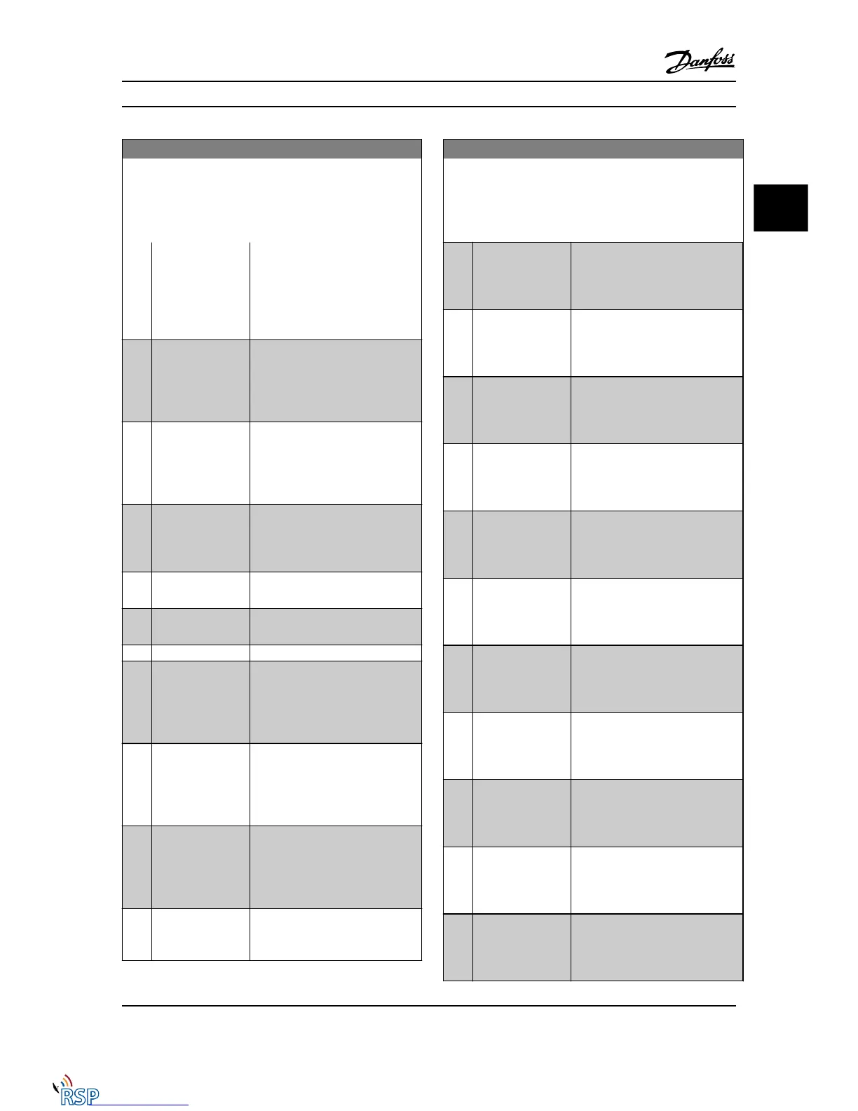
5-40 Function Relay
Array [9]
(Relay 1 [0], Relay 2 [1], Relay 3 [2] (MCB 113), Relay 4 [3] (MCB
113), Relay 5 [4] (MCB 113), Relay 6 [5] (MCB 113), Relay 7 [6]
(MCB 105), Relay 8 [7] (MCB 105), Relay 9 [8] (MCB 105))
Option: Function:
impact in the Adjustable frequency
drive. Typical application: controlling
auxiliary device from the serial
communication bus. The function is
valid when FC profile [0] in
8-10 Control Word Profile is selected.
[38] Motor feedback
error
Failure in the speed feedback loop
from motor running in closed-loop.
The output can eventually be used
to prepare switching the drive in
open-loop in emergency case.
[39] Tracking error When the difference between
calculated speed and actual speed in
4-35 Tracking Error is larger than
selected the digital output/relay is
active.
[40] Out of ref range Active when the actual speed is
outside settings in 4-52 Warning
Speed Low to 4-55 Warning Reference
High.
[41] Below reference,
low
Active when actual speed is below
speed reference setting.
[42] Above ref, high Active when actual speed is above
speed reference setting.
[43] Extended PID Limit
[45] Bus ctrl. Controls digital output/relay via bus.
The state of the output is set in
5-90 Digital & Relay Bus Control. The
output state is retained in the event
of bus timeout.
[46] Bus ctrl, 1 if timeout Controls output via bus. The state of
the output is set in 5-90 Digital &
Relay Bus Control. In the event of a
bus timeout, the output state is set
high (On).
[47] Bus ctrl, 0 if timeout Controls output via bus. The state of
the output is set in 5-90 Digital &
Relay Bus Control. In the event of a
bus timeout, the output state is set
low (Off).
[51] MCO controlled Active when a MCO 302 or MCO 305
is connected. The output is
controlled from option.
5-40 Function Relay
Array [9]
(Relay 1 [0], Relay 2 [1], Relay 3 [2] (MCB 113), Relay 4 [3] (MCB
113), Relay 5 [4] (MCB 113), Relay 6 [5] (MCB 113), Relay 7 [6]
(MCB 105), Relay 8 [7] (MCB 105), Relay 9 [8] (MCB 105))
Option: Function:
[60] Comparator 0 See parameter group 13-1* (Smart
Logic Control). If Comparator 0 in
SLC is TRUE, the output will go high.
Otherwise, it will be low.
[61] Comparator 1 See parameter group 13-1* (Smart
Logic Control). If Comparator 1 in
SLC is TRUE, the output will go high.
Otherwise, it will be low.
[62] Comparator 2 See parameter group 13-1* (Smart
Logic Control). If Comparator 2 in
SLC is TRUE, the output will go high.
Otherwise, it will be low.
[63] Comparator 3 See parameter group 13-1* (Smart
Logic Control). If Comparator 3 in
SLC is TRUE, the output will go high.
Otherwise, it will be low.
[64] Comparator 4 See parameter group 13-1* (Smart
Logic Control). If Comparator 4 in
SLC is TRUE, the output will go high.
Otherwise, it will be low.
[65] Comparator 5 See parameter group 13-1* (Smart
Logic Control). If Comparator 5 in
SLC is TRUE, the output will go high.
Otherwise, it will be low.
[70] Logic rule 0 See parameter group 13-4*(Smart
Logic Control). If Logic Rule 0 in SLC
is TRUE, the output will go high.
Otherwise, it will be low.
[71] Logic rule 1 See parameter group 13-4*(Smart
Logic Control). If Logic Rule 1 in SLC
is TRUE, the output will go high.
Otherwise, it will be low.
[72] Logic rule 2 See parameter group 13-4*(Smart
Logic Control). If Logic Rule 2 in SLC
is TRUE, the output will go high.
Otherwise, it will be low.
[73] Logic rule 3 See parameter group 13-4*(Smart
Logic Control). If Logic Rule 3 in SLC
is TRUE, the output will go high.
Otherwise, it will be low.
[74] Logic rule 4 See parameter group 13-4*(Smart
Logic Control). If Logic Rule 4 in SLC
is TRUE, the output will go high.
Otherwise, it will be low.
Parameter Descriptions FC 300 Programming Guide
MG33MD22 - VLT
®
is a registered Danfoss trademark 3-61
3
3

 Loading...


