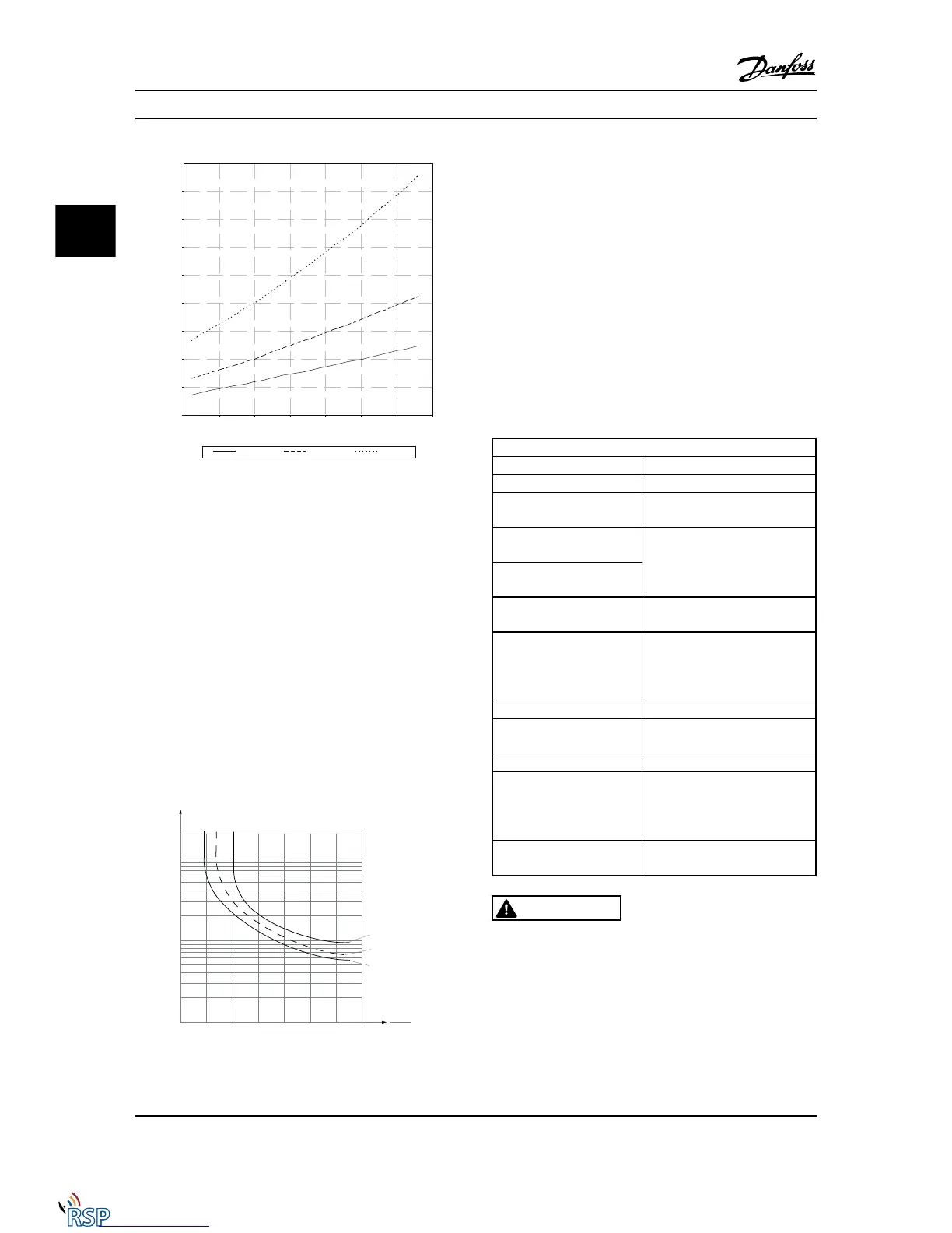
Figure 3.5 KTY type selection
KTY Sensor 1: KTY 84-1 with 1kΩ at 212°F [100°C]
KTY Sensor 2: KTY 81-1, KTY 82-1 with 1kΩ at 77°F [25°C]
KTY Sensor 3: KTY 81-2, KTY 82-2 with 2kΩ at 77°F [25°C]
NOTE!
If the temperature of the motor is utilized through a
thermistor or KTY sensor, the PELV is not complied with in
the event of short circuits between motor windings and
sensor. In order to comply with PELV, the sensor must be
extra isolated.
3.3.10.3 ETR
The calculations estimate the need for a lower load at
lower speed due to less cooling from the fan incorporated
in the motor.
Figure 3.6 ETR profile
3.3.10.4
ATEX ETR
The B option MCB 112 PTC Thermistor option offers ATEX
approved monitoring of motor temperature. Alternatively,
an external ATEX approved PTC protection device can be
used.
NOTE!
Only ATEX Ex-e approved motors may be used for this
function. See motor nameplate, approval certificate, data
sheet or contact motor supplier.
When controlling an Ex-e motor with “Increased Safety”, it
is important to ensure certain limitations. The parameters
that must be programmed are presented in the following
application example.
Parameters
Function Setting
1-90 Motor Thermal Protection
[20] ATEX ETR
1-94 ATEX ETR cur.lim. speed
reduction
20%
1-98 ATEX ETR interpol. points
freq.
Motor nameplate
1-99 ATEX ETR interpol points
current
1-23 Motor Frequency Enter the same value as for
4-19 Max Output Frequency
4-19 Max Output Frequency
Motor nameplate, possibly
reduced for long motor cables,
sinus filter or reduced supply
voltage
4-18 Current Limit
Forced to 150% by 1-90 [20]
5-15 Terminal 33 Digital
Input
[80] PTC Card 1
5-19 Terminal 37 Safe Stop
[4] PTC 1 Alarm
14-01 Switching Frequency
Check that the default value fulfils
the requirement for Motor
nameplate. If not, use the sine-
wave filter.
14-26 Trip Delay at Inverter
Fault
0
CAUTION
It is mandatory to compare the minimum switching
frequency requirement stated by the motor manufacturer
to the minimum switching frequency of the Adjustable
frequency drive, the default value in 14-01 Switching
Frequency. If the Adjustable frequency drive does not meet
this requirement, a sine-wave filter must be used.
More information about ATEX ETR Thermal Monitoring can
be found in the Application Note MN.33.GX.YY.
Parameter Descriptions FC 300 Programming Guide
3-26 MG33MD22 - VLT
®
is a registered Danfoss trademark
3
3

 Loading...


