13-16 RS-FF Operand R
Option: Function:
[43] Ok key
[44] Reset key
[45] Left key
[46] Right key
[47] Up key
[48] Down key
[50] Comparator 4
[51] Comparator 5
[60] Logic rule 4
[61] Logic rule 5
[70] SL Time-out 3
[71] SL Time-out 4
[72] SL Time-out 5
[73] SL Time-out 6
[74] SL Time-out 7
[75] Start command given
[76] Digital input x30/2
[77] Digital input x30/3
[78] Digital input x30/4
[79] Digital input x46/1
[80] Digital input x46/3
[81] Digital input x46/5
[82] Digital input x46/7
[83] Digital input x46/9
[84] Digital input x46/11
[85] Digital input x46/13
[90] ATEX ETR cur. warning
[91] ATEX ETR cur. alarm
[92] ATEX ETR freq. warning
[93] ATEX ETR freq. alarm
[94] RS Flipflop 0
[95] RS Flipflop 1
[96] RS Flipflop 2
[97] RS Flipflop 3
[98] RS Flipflop 4
[99] RS Flipflop 5
[100] RS Flipflop 6
[101] RS Flipflop 7
3.14.5 13-2* Timers
Use the result (TRUE or FALSE) from timers directly to
define an event (see 13-51 SL Controller Event), or as
Boolean input in a logic rule (see 13-40 Logic Rule Boolean
1, 13-42 Logic Rule Boolean 2 or 13-44 Logic Rule Boolean 3).
A timer is only FALSE when started by an action (i.e., Start
timer 1 [29]) until the timer value entered in this
parameter is elapsed. Then it becomes TRUE again.
All parameters in this parameter group are array
parameters with index 0 to 2. Select index 0 to program
Timer 0, select index 1 to program Timer 1, and so on.
13-20 SL Controller Timer
Range: Function:
Application
dependent*
[Application
dependant]
Enter the value to define the
duration of the FALSE output
from the programmed timer. A
timer is only FALSE if it is started
by an action (i.e., Start timer 1
[29]) and until the given timer
value has elapsed.
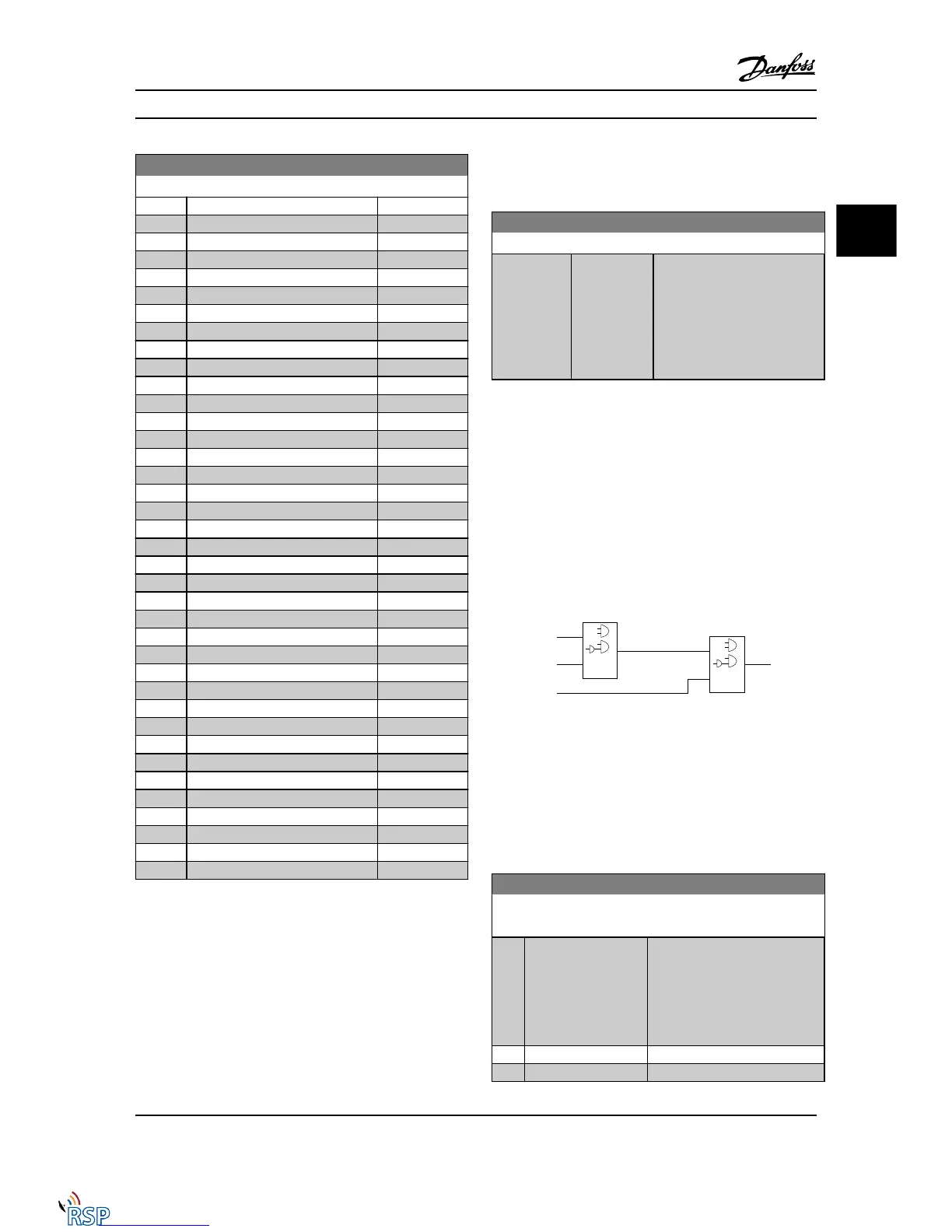
3.14.6 13-4* Logic Rules
Combine up to three boolean inputs (TRUE / FALSE inputs)
from timers, comparators, digital inputs, status bits and
events using the logical operators AND, OR, and NOT.
Select Boolean inputs for the calculation in 13-40 Logic Rule
Boolean 1, 13-42 Logic Rule Boolean 2 and 13-44 Logic Rule
Boolean 3. Define the operators used to logically combine
the selected inputs in 13-41 Logic Rule Operator 1 and
13-43 Logic Rule Operator 2.
Priority of calculation
The results of 13-40 Logic Rule Boolean 1, 13-41 Logic Rule
Operator 1 and 13-42 Logic Rule Boolean 2 are calculated
first. The outcome (TRUE / FALSE) of this calculation is
combined with the settings of 13-43 Logic Rule Operator 2
and 13-44 Logic Rule Boolean 3, yielding the final result
(TRUE / FALSE) of the logic rule.
13-40 Logic Rule Boolean 1
Array [6]
Option: Function:
[0] * False Select the first Boolean (TRUE or
FALSE) input for the selected logic
rule.
See 13-01 Start Event ([0] - [61])
and 13-02 Stop Event ([70] - [75])
for further description.
[1] True
[2] Running
Parameter Descriptions FC 300 Programming Guide
MG33MD22 - VLT
®
is a registered Danfoss trademark 3-119
3
3

 Loading...


