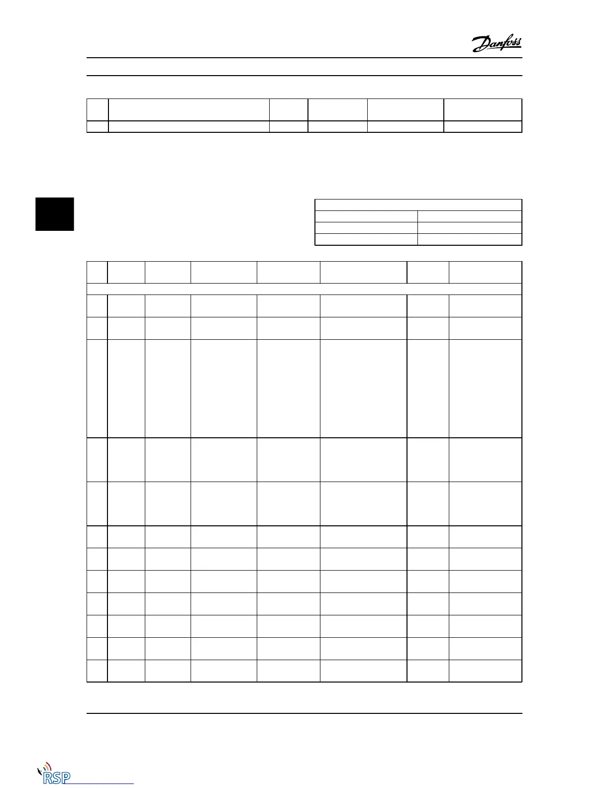
No. Description Warning Alarm/Trip Alarm/Trip Lock Parameter
Reference
251 New Type Code X X
Table 5.1 Alarm/Warning code list
(X) Dependent on parameter
1) Cannot be Auto reset via 14-20 Reset Mode
A trip is the action when an alarm has appeared. The trip
will coast the motor and can be reset by pressing the reset
button or make a reset by a digital input (parameter group
5-1* [1]). The original event that caused an alarm cannot
damage the Adjustable frequency drive or cause
dangerous conditions. A trip lock is an action when an
alarm occurs that may cause damage to theAdjustable
frequency drive or connected parts. A trip lock situation
can only be reset by power cycling.
LED indication
Warning yellow
Alarm flashing red
Trip locked yellow and red
Bit Hex Dec Alarm Word Alarm Word 2 Warning Word Warning
Word 2
Extended
Status Word
Alarm Word Extended Status Word
0 00000001 1 Brake Check (A28) ServiceTrip, Read/
Write
Brake Check (W28) reserved Ramping
1 00000002 2 Heatsink temp.
(A29)
ServiceTrip,
(reserved)
Heatsink temp. (W29) reserved AMA Running
2 00000004 4 Ground Fault (A14) ServiceTrip,
Typecode/
Sparepart
Ground Fault (W14) reserved Start CW/CCW
NOT start_possible
start_possible is
active, when the DI
selections [12] OR
[13] are active and
the requested
direction matches the
reference sign.
3 00000008 8 Ctrl.Card Temp
(A65)
ServiceTrip,
(reserved)
Ctrl.Card Temp (W65) reserved Slow-down
slow-down command
active, e.g., via CTW
bit 11 or DI
4 00000010 16 Ctrl. Word TO (A17) ServiceTrip,
(reserved)
Ctrl. Word TO (W17) Catch Up
catch up command
active, e.g., via CTW
bit 12 or DI
5 00000020 32 Overcurrent (A13) reserved Overcurrent (W13) reserved Feedback High
feedback > p4-57
6 00000040 64 Torque Limit (A12) reserved Torque Limit (W12) reserved Feedback Low
feedback < p4-56
7 00000080 128 Motor Th Over
(A11)
reserved Motor Th Over (W11) reserved Output Current High
current > p4-51
8 00000100 256 Motor ETR Over
(A10)
reserved Motor ETR Over (W10) reserved Output Current Low
current < p4-50
9 00000200 512 Inverter Overld.
(A9)
reserved Inverter Overld (W9) reserved Output Freq High
speed > p4-53
10 00000400 1,024 DC under-volt (A8) reserved DC under-volt (W8) Output Freq Low
speed < p4-52
11 00000800 2,048 DC overvoltage
(A7)
reserved DC overvoltage (W7) Brake Check OK
brake test NOT ok
Troubleshooting FC 300 Programming Guide
5-4 MG33MD22 - VLT
®
is a registered Danfoss trademark
55

 Loading...


