Usually the resolver feedback is used as motor feedback
from permanent magnet motors with 1-01 Motor Control
Principle set to Flux with motor feedback.
Resolver parameters cannot be adjusted while the motor is
running.
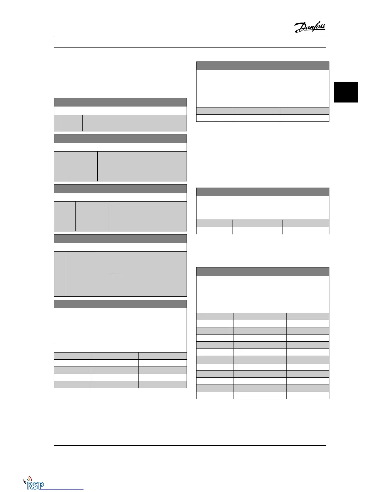
17-50 Poles
Range: Function:
2* [2 - 2 ] Set the number of poles on the resolver.
The value is stated in the data sheet for resolvers.
17-51 Input Voltage
Range: Function:
7.0 V* [2.0 - 8.0 V] Set the input voltage to the resolver. The
voltage is stated as an RMS value.
The value is stated in the data sheet for
resolvers.
17-52 Input Frequency
Range: Function:
10.0 kHz* [2.0 - 15.0
kHz]
Set the input frequency to the
resolver.
The value is stated in the data sheet
for resolvers.
17-53 Transformation Ratio
Range: Function:
0.5* [0.1 - 1.1 ] Set the transformation ratio for the resolver.
The transformation ration is:
T
ratio
=
V
Out
V
In
The value is stated in the data sheet for
resolvers.
17-56 Encoder Sim. Resolution
Set the resolution and activate the encoder emulation function
(generation of encoder signals from the measured position from
a resolver). Needed when necessary to transfer the speed or
position information from one drive to another. To disable the
function, select [0].
Option: Function:
[0] * Disabled
[1] 512
[2] 1024
[3] 2048
[4] 4096
17-59 Resolver Interface
Activate the MCB 103 resolver option when the resolver
parameters are selected.
To avoid damage to resolvers, 17-50 Poles – 17-53 Transformation
Ratio must be adjusted before activating this parameter.
Option: Function:
[0] * Disabled
[1] Enabled
3.18.4 17-6* Monitoring and Application
This parameter group is used for selecting additional
functions when the MCB 102 Encoder option or MCB 103
Resolver option is fitted into option slot B as speed
feedback.
Monitoring and application parameters cannot be adjusted
while the motor is running.
17-60 Feedback Direction
Change the detected encoder rotation direction without
changing the wiring to the encoder.
Option: Function:
[0] * Clockwise
[1] Counter clockwise
NOTE!
This parameter cannot be adjusted while the motor is
running.
17-61 Feedback Signal Monitoring
Select which reaction the Adjustable frequency drive should take
if a faulty encoder signal is detected.
The encoder function in 17-61 Feedback Signal Monitoring is an
electrical check of the hardware circuit in the encoder system.
Option: Function:
[0] Disabled
[1] * Warning
[2] Trip
[3] Jog
[4] Freeze Output
[5] Max Speed
[6] Switch to Open Loop
[7] Select Setup 1
[8] Select Setup 2
[9] Select Setup 3
[10] Select Setup 4
[11] stop & trip
Parameter Descriptions FC 300 Programming Guide
MG33MD22 - VLT
®
is a registered Danfoss trademark 3-149
3
3

 Loading...


