16-85 FC Port CTW 1
Range: Function:
0 * [0 - 65535 ] View the two-byte control word (CTW)
received from the bus master. Interpretation
of the control word depends on the Serial
communication bus option installed and the
control word profile selected in 8-10 Control
Profile.
16-86 FC Port REF 1
Range: Function:
0 * [-200 -
200 ]
View the two-byte status word (STW) sent to
the bus master. Interpretation of the status
word depends on the serial communication
bus option installed and the control word
profile selected in 8-10 Control Profile.
3.17.6 16-9* Diagnosis Readouts
16-90 Alarm Word
Range: Function:
0 * [0 - 4294967295 ] View the alarm word sent via the serial
communication port in hex code.
16-91 Alarm Word 2
Range: Function:
0* [0 - 4294967295 ] View the alarm word sent via the serial
communication port in hex code.
16-92 Warning Word
Range: Function:
0 * [0 - 4294967295 ] View the warning word sent via the
serial communication port in hex code.
16-93 Warning Word 2
Range: Function:
0* [0 - 4294967295 ] View the warning word sent via the serial
communication port in hex code.
16-94 Ext. Status Word
Range: Function:
0* [0 - 4294967295 ] Returns the extended warning word sent
via the serial communication port in hex
code.
16-95 Ext. Status Word 2
Range: Function:
0 * [0 - 4294967295 ] Returns the extended warning word 2
sent via the serial communication port
in hex code.
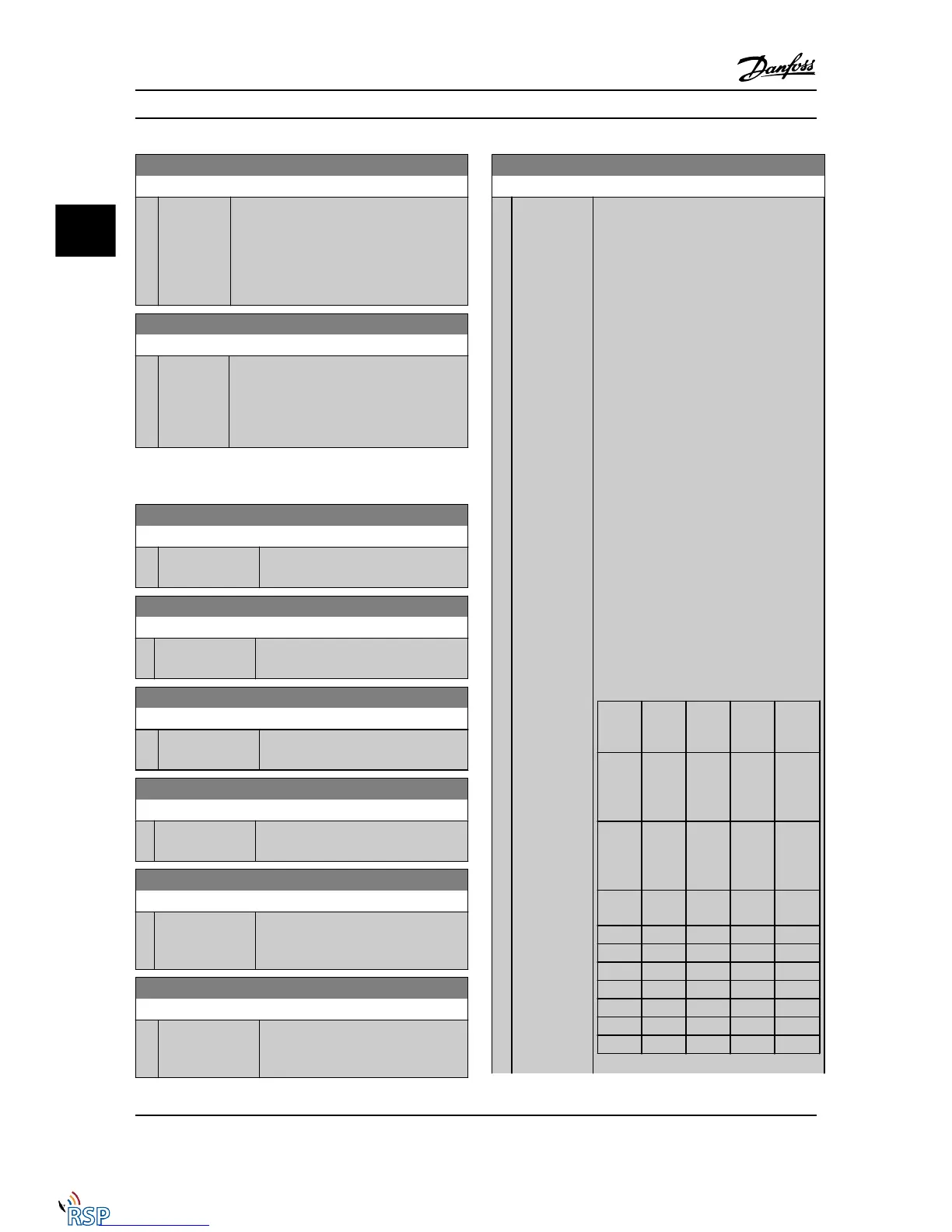
16-96 Maintenance Word
Range: Function:
0
*
[0 -
4294967295 ]
Readout of the Preventive Maintenance
Word. The bits reflect the status for the
programmed preventive maintenance events
in parameter group 23-1*. 13 bits represent
combinations of all the possible items:
•
Bit 0: Motor bearings
•
Bit 1: Pump bearings
•
Bit 2: Fan bearings
•
Bit 3: Valve
•
Bit 4: Pressure transmitter
•
Bit 5: Flow transmitter
•
Bit 6: Temperature transmitter
•
Bit 7: Pump seals
•
Bit 8: Fan belt
•
Bit 9: Filter
•
Bit 10: Drive cooling fan
•
Bit 11: Drive system health check
•
Bit 12: Warranty
•
Bit 13: Maintenance Text 0
•
Bit 14: Maintenance Text 1
•
Bit 15: Maintenance Text 2
•
Bit 16: Maintenance Text 3
•
Bit 17: Maintenance Text 4
Positio
n 4⇒
Valve Fan
bearing
s
Pump
bearing
s
Motor
bearing
s
Positio
n 3 ⇒
Pump
seals
Temper
ature
transmi
tter
Flow
transmi
tter
Pressur
e
transmi
tter
Positio
n 2 ⇒
Drive
system
health
check
Drive
cooling
fan
Filter Fan
belt
Positio
n 1⇒
Warrant
y
0
hex
- - - -
1
hex
- - - +
2
hex
- - + -
3
hex
- - + +
4
hex
- + - -
5
hex
- + - +
6
hex
- + + -
Parameter Descriptions FC 300 Programming Guide
3-146 MG33MD22 - VLT
®
is a registered Danfoss trademark
3
3

 Loading...


