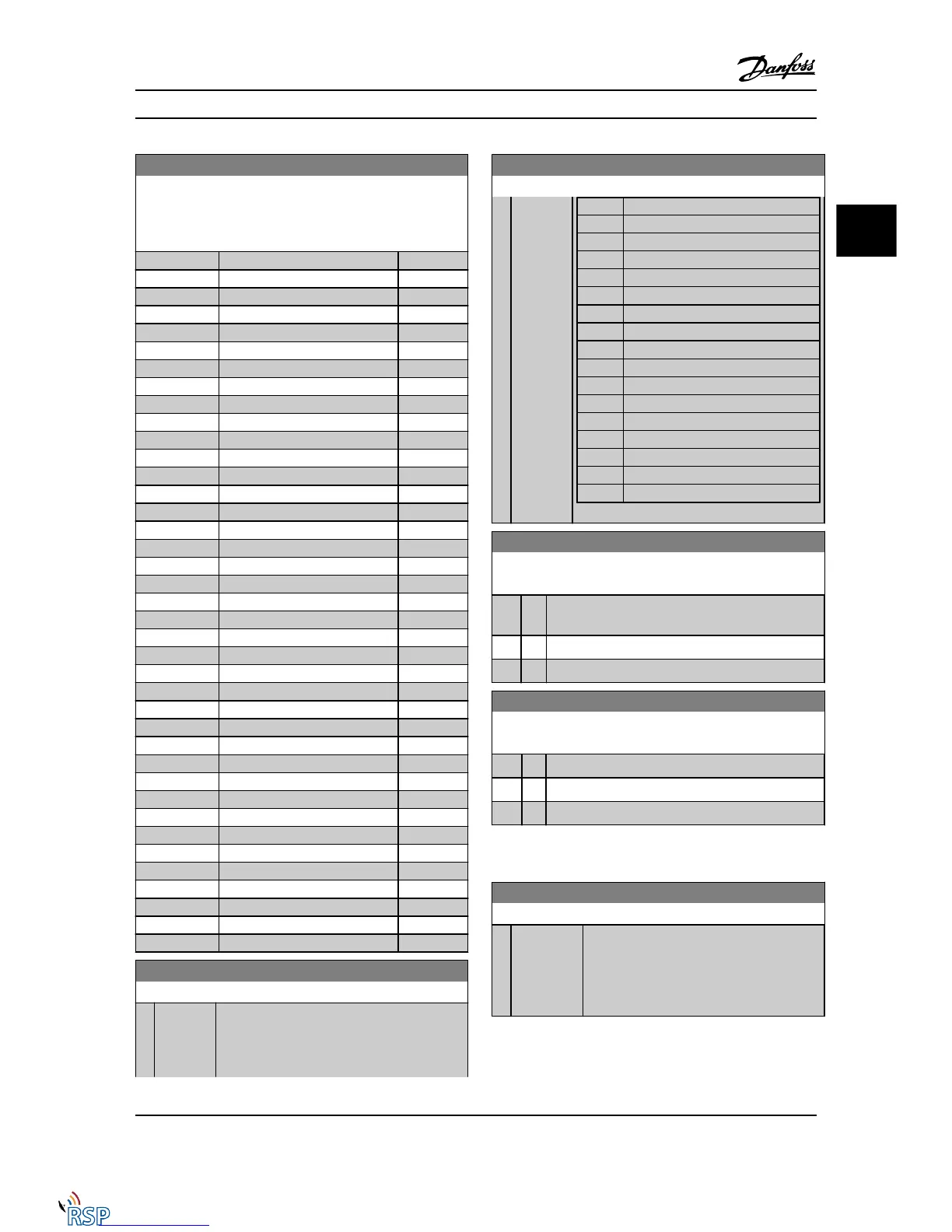
10-12 Process Data Config Read
Select the process read data for I/O assembly instances 101/151.
Elements [2] and [3] of this array can be selected. Elements [0]
and [1] of the array are fixed.
Option: Function:
[1684] Comm. Option STW
[1690] Alarm Word
[1691] Alarm Word 2
[1692] Warning Word
[1693] Warning Word 2
[1694] Ext. Status Word
[1860] Digital Input 2
[3421] PCD 1 Read from MCO
[3422] PCD 2 Read from MCO
[3423] PCD 3 Read from MCO
[3424] PCD 4 Read from MCO
[3425] PCD 5 Read from MCO
[3426] PCD 6 Read from MCO
[3427] PCD 7 Read from MCO
[3428] PCD 8 Read from MCO
[3429] PCD 9 Read from MCO
[3430] PCD 10 Read from MCO
[3440] Digital Inputs
[3441] Digital Outputs
[3450] Actual Position
[3451] Commanded Position
[3452] Actual Master Position
[3453] Slave Index Position
[3454] Master Index Position
[3455] Curve Position
[3456] Track Error
[3457] Synchronizing Error
[3458] Actual Velocity
[3459] Actual Master Velocity
[3460] Synchronizing Status
[3461] Axis Status
[3462] Program Status
[3464] MCO 302 Status
[3465] MCO 302 Control
[3470] MCO Alarm Word 1
[3471] MCO Alarm Word 2
[4280] Safe Option Status
[4285] Active Safe Func.
[4286] Safe Option Info
10-13 Warning Parameter
Range: Function:
0* [0 -
65535 ]
View a DeviceNet-specific warning word. One bit
is assigned to every warning. Please refer to the
DeviceNet Instruction Manual (MG.33.DX.YY) for
further information.
10-13 Warning Parameter
Range: Function:
Bit: Meaning:
0 BusNetwork not active
1 Explicit connection timeout
2 I/O connection
3 Retry limit reached
4 Actual is not updated
5 CAN bus off
6 I/O send error
7 Initialization error
8 No bus supply
9 Bus off
10 Error passive
11 Error warning
12 Duplicate MAC ID Error
13 RX queue overrun
14 TX queue overrun
15 CAN overrun
10-14 Net Reference
Read only from LCP
Option: Function:
Select the reference source in instance 21/71 and
20/70.
[0] * Off Enables reference via analog/digital inputs.
[1] On Enables reference via the serial communication bus.
10-15 Net Control
Read only from LCP
Option: Function:
Select the control source in Instance 21/71 and 20/70.
[0] * Off Enables control via analog/digital inputs.
[1] On Enable control via the serial communication bus.
3.12.3 10-2* COS Filters
10-20 COS Filter 1
Range: Function:
0* [0 - 65535 ] Enter the value for COS Filter 1 to set up the
filter mask for the status word. When operating
in COS (Change-Of-State), this function filters
out bits in the status word that should not be
sent if they change.
Parameter Descriptions FC 300 Programming Guide
MG33MD22 - VLT
®
is a registered Danfoss trademark 3-103
3
3

 Loading...


