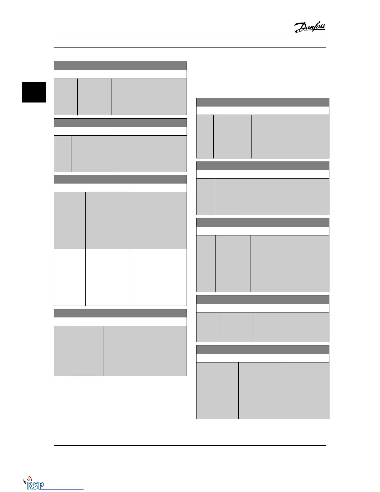
6-13 Terminal 53 High Current
Range: Function:
20.00 mA* [ par. 6-12 -
20.00 mA]
Enter the high current value
corresponding to the high
reference/feedback set in
6-15 Terminal 53 High Ref./Feedb.
Value.
6-14 Terminal 53 Low Ref./Feedb. Value
Range: Function:
0.000 * [-999999.999 -
999999.999 ]
Enter the analog input scaling
value that corresponds to the low
voltage/low current set in
6-10 Terminal 53 Low Voltage and
6-12 Terminal 53 Low Current.
6-15 Terminal 53 High Ref./Feedb. Value
Range: Function:
Application
dependent*
[-999999.999 -
999999.999
ReferenceFeed-
backUnit]
Enter the analog input
scaling value that
corresponds to the
maximum reference
feedback value set in
6-11 Terminal 53 High
Voltage and 6-13 Terminal
53 High Current.
Application
dependent*
[-999999.999 -
999999.999
ReferenceFeed-
backUnit]
Enter the analog input
scaling value that
corresponds to the
maximum reference
feedback value set in
6-11 Terminal 53 High
Voltage and 6-13 Terminal
53 High Current.
6-16 Terminal 53 Filter Time Constant
Range: Function:
0.001 s* [0.001 -
10.000 s]
Enter the time constant. This is a first-
order digital low pass filter time
constant for suppressing electrical noise
in terminal 53. A high time constant
value improves dampening but also
increases the time delay through the
filter.
NOTE!
This parameter cannot be adjusted while the motor is
running.
3.8.3 6-2* Analog Input 2
Parameters for configuring the scaling and limits for
analog input 2 (terminal 54).
6-20 Terminal 54 Low Voltage
Range: Function:
0.07 V* [Application
dependant]
Enter the low voltage value. This
analog input scaling value should
correspond to the minimum
reference value, set in 3-02 Minimum
Reference. See also the section
Reference Handling.
6-21 Terminal 54 High Voltage
Range: Function:
10.00 V* [ par. 6-20 -
10.00 V]
Enter the high voltage value. This
analog input scaling value should
correspond to the high reference/
feedback value set in 6-25 Terminal 54
High Ref./Feedb. Value.
6-22 Terminal 54 Low Current
Range: Function:
0.14
mA*
[Application
dependant]
Enter the low current value. This
reference signal should correspond to
the minimum reference value, set in
3-02 Minimum Reference. The value
must be set at >2mA in order to
activate the Live Zero Timeout
Function in 6-01 Live Zero Timeout
Function.
6-23 Terminal 54 High Current
Range: Function:
20.00 mA* [ par. 6-22 -
20.00 mA]
Enter the high current value
corresponding to the high reference/
feedback value set in 6-25 Terminal
54 High Ref./Feedb. Value.
6-24 Terminal 54 Low Ref./Feedb. Value
Range: Function:
0 ReferenceFeed-
backUnit*
[-999999.999 -
999999.999
ReferenceFeed-
backUnit]
Enter the analog
input scaling value
that corresponds to
the minimum
reference feedback
value set in
3-02 Minimum
Reference.
Parameter Descriptions FC 300 Programming Guide
3-70 MG33MD22 - VLT
®
is a registered Danfoss trademark
3
3

 Loading...


