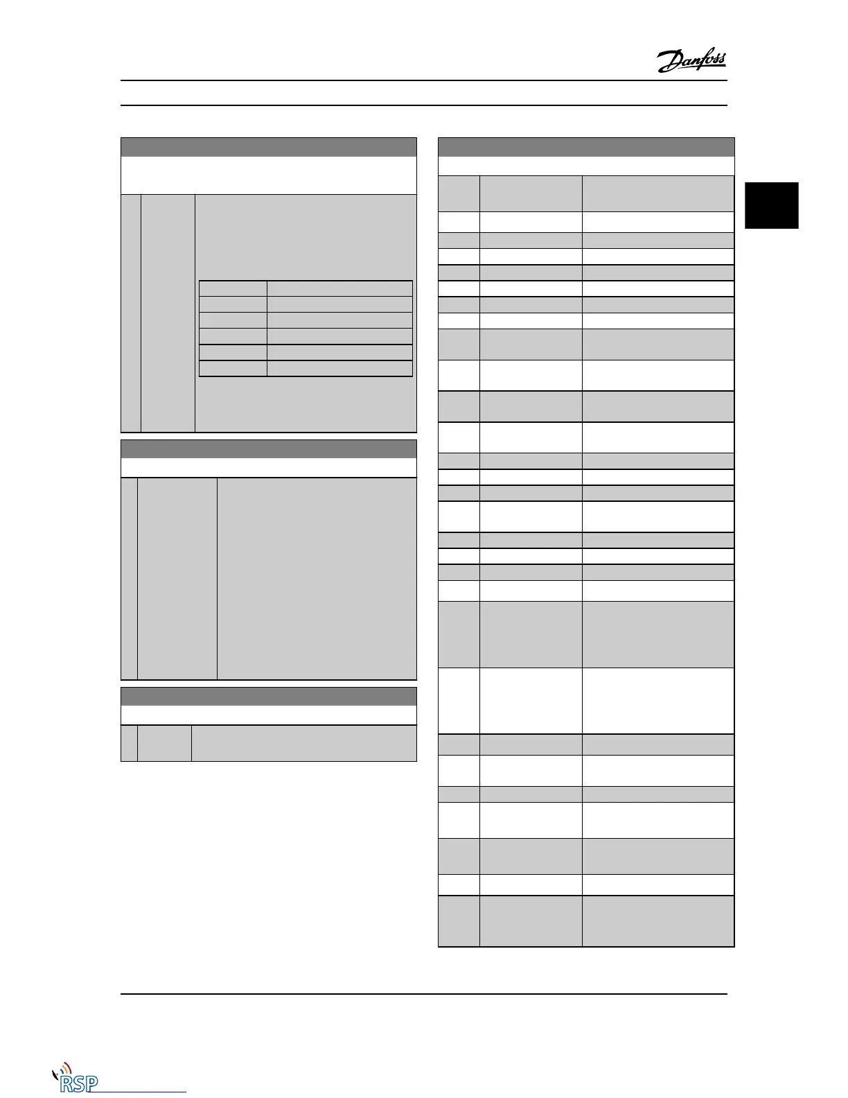
0-13 Readout: Linked Set-ups
Array [5]
Range: Function:
0 * [0 - 255 ] View a list of all the set-ups linked by means of
0-12 This Set-up Linked to. The parameter has one
index for each parameter set-up. The parameter
value displayed for each index represents which
set-ups are linked to that parameter set-up.
Index LCP value
0 {0}
1 {1,2}
2 {1,2}
3 {3}
4 {4}
Table 3.2 Example: Set-up 1 and Set-up 2 are
linked
0-14 Readout: Edit Set-ups / Channel
Range: Function:
0* [-2147483648 -
2147483647 ]
View the setting of 0-11 Edit Set-up for each
of the four different communication
channels. When the number is displayed in
hex, as it is in the LCP, each number
represents one channel.
Numbers 1-4 represent a set-up number; ‘F’
means factory setting; and ‘A’ means active
set-up. The channels are, from right to left:
LCP , FC-bus, USB, HPFB1-5.
Example: The number AAAAAA21h means
that the FC bus selected Set-up 2 in
0-11 Edit Set-up, the LCP selected Set-up 1
and all others used the active set-up.
0-15 Readout: actual setup
Range: Function:
0* [0 - 255 ] Makes it possible to read out the active set-up,
also when multi set-up is selected in par. 0-10.
3.2.3 0-2* LCP Display
Define the variables displayed in the Graphical Local
Control Panel.
NOTE!
Please refer to 0-37 Display Text 1, 0-38 Display Text 2 and
0-39 Display Text 3 for information on how to write display
texts.
0-20 Display Line 1.1 Small
Option: Function:
Select a variable for display in
line 1, left position.
[0] * None No display value selected.
[9] Performance Monitor
[15] Readout: actual setup
[37] Display Text 1
[38] Display Text 2
[39] Display Text 3
[748] PCD Feed Forward
[953] Profibus Warning
Word
[1005] Readout Transmit
Error Counter
[1006] Readout Receive
Error Counter
[1007] Readout Bus Off
Counter
[1013] Warning Parameter
[1230] Warning Parameter
[1472] Legacy Alarm Word
[1473] Legacy Warning
Word
[1474] Leg. Ext. Status Word
[1501] Running Hours
[1502] kWh Counter
[1600] Control Word Present control word
[1601] Reference [Unit] Total reference (sum of digital/
analog/preset/bus/freeze ref./
catch up and slow-down) in
selected unit.
[1602] Reference % Total reference (sum of digital/
analog/preset/bus/freeze ref./
catch up and slow-down) in
percent.
[1603] Status Word Present status word.
[1605] Main Actual Value
[%]
Actual value as a percentage.
[1609] Custom Readout
[1610] Power [kW] Actual power consumed by the
motor in kW.
[1611] Power [hp] Actual power consumed by the
motor in HP.
[1612] Motor Voltage Voltage supplied to the motor.
[1613] Frequency Motor frequency, i.e., the output
frequency from the Adjustable
frequency drive in Hz
Parameter Descriptions FC 300 Programming Guide
MG33MD22 - VLT
®
is a registered Danfoss trademark 3-5
3
3

 Loading...


