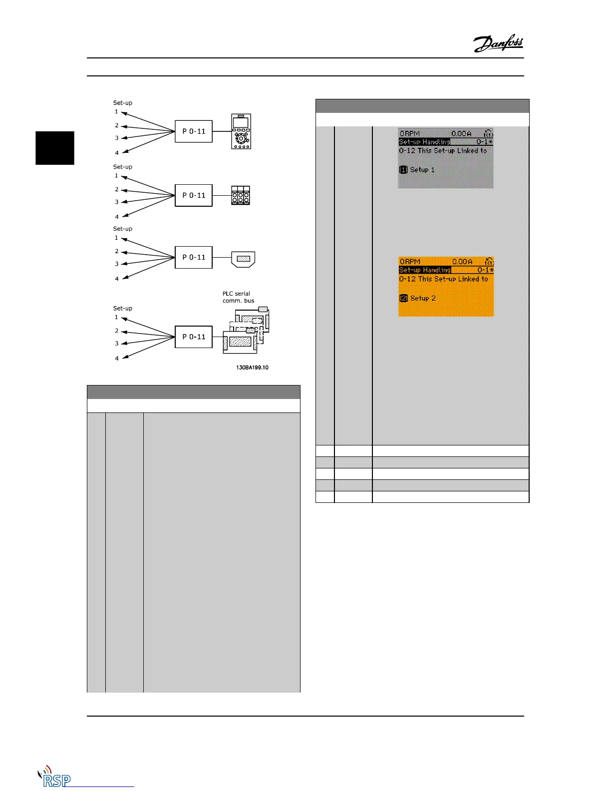
0-12 This Set-up Linked to
Option: Function:
To enable conflict-free changes from one set-up
to another during operation, link set-ups
containing parameters that are not changeable
during operation. The link will ensure the
proper synchronization of the ‘not changeable
during operation’ parameter values when
moving from one set-up to another during
operation. ‘Not changeable during operation’
parameters can be identified by the label FALSE
in the parameter lists in the section Parameter
Lists.
0-12 This Set-up Linked to is used by Multi set-
up in 0-10 Active Set-up. Multi set-up is used to
move from one set-up to another during
operation (i.e., while the motor is running).
Example:
Use Multi set-up to shift from Set-up 1 to Set-
up 2 while the motor is running. Program in
Set-up 1 first, then ensure that Set-up 1 and
Set-up 2 are synchronized (or ‘linked’). Synchro-
nization can be performed in two ways:
1. Change the edit set-up to Set-up 2 [2] in
0-11 Edit Set-up and set 0-12 This Set-up Linked
to to Set-up 1 [1]. This will start the linking
(synchronizing) process.
0-12 This Set-up Linked to
Option: Function:
OR
2. While still in Set-up 1, copy Set-up 1 to Set-
up 2. Then set 0-12 This Set-up Linked to to Set-
up 2 [2]. This will start the linking process.
After the link is complete, 0-13 Readout: Linked
Set-ups will read {1,2} to indicate that all ‘not
changeable during operation’ parameters are
now the same in Set-up 1 and Set-up 2. If there
are changes to a "not changeable during
operation" parameter, e.g., 1-30 Stator Resistance
(Rs) in Set-up 2, they will also be changed
automatically in Set-up 1. A switch between
Set-up 1 and Set-up 2 during operation is now
possible.
[0]
* Not linked
[1] Set-up 1
[2] Set-up 2
[3] Set-up 3
[4] Set-up 4
Parameter Descriptions FC 300 Programming Guide
3-4 MG33MD22 - VLT
®
is a registered Danfoss trademark
3
3

 Loading...


