NOTE!
This parameter cannot be adjusted while the motor is
running.
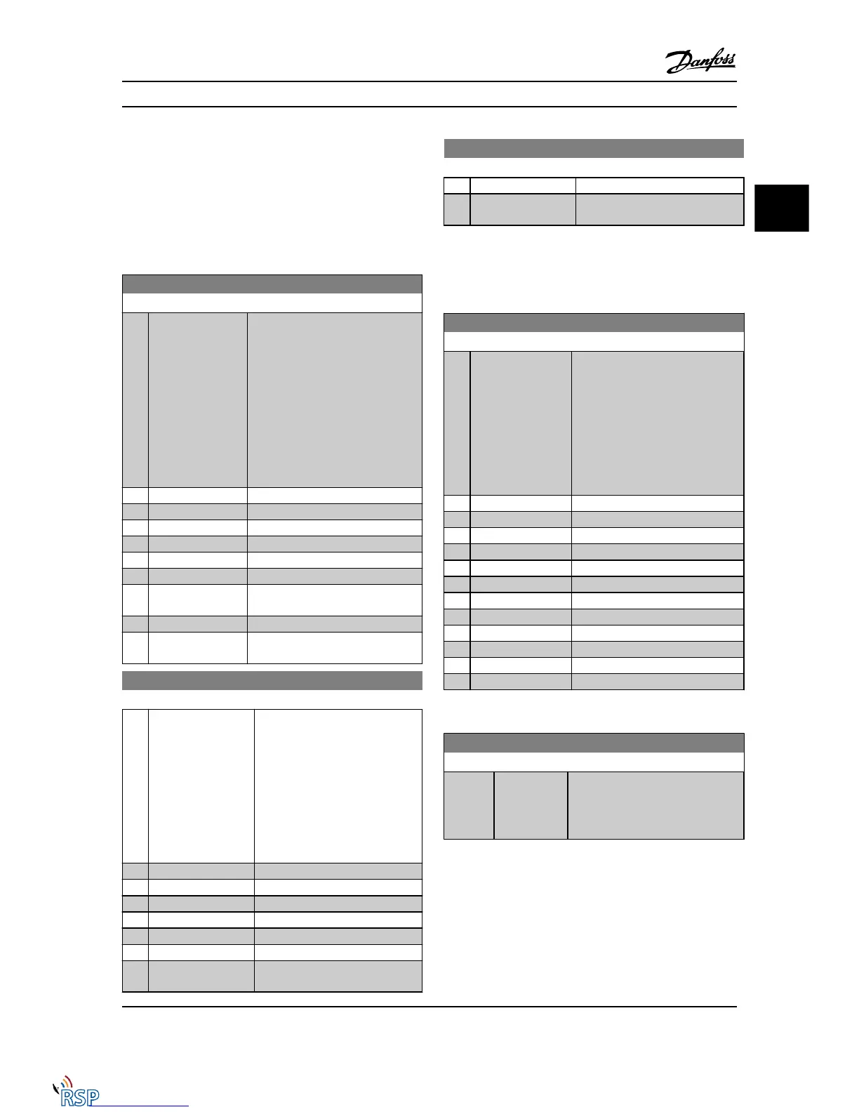
NOTE!
Max. output frequency cannot exceed 10% of the inverter
switching frequency (14-01 Switching Frequency).
4-20 Torque Limit Factor Source
Option: Function:
Select an analog input for scaling the
settings in 4-16 Torque Limit Motor
Mode and 4-17 Torque Limit Generator
Mode from 0% to 100% (or inverse).
The signal levels corresponding to
0% and 100% are defined in the
analog input scaling, e.g., parameter
group 6-1*. This parameter is only
active when 1-00 Configuration Mode
is in Speed Open-loop or Speed
Closed-loop.
[0] * No function
[2] Analog in 53
[4] Analog in 53 inv
[6] Analog in 54
[8] Analog in 54 inv
[10] Analog in X30-11
[12] Analog in X30-11
inv
[14] Analog in X30-12
[16] Analog in X30-12
inv
4-21 Speed Limit Factor Source Option
Option: Function:
Select an analog input for scaling
the settings in 4-19 Max Output
Frequency from 0% to 100% (or vice
versa). The signal levels
corresponding to 0% and 100% are
defined in the analog input scaling,
e.g., parameter group 6-1*. This
parameter is only active when
1-00 Configuration Mode is in Torque
Mode.
[0] * No function
[2] Analog input 53
[4] Analog input 53 inv
[6] Analog input 54
[8] Analog input 54 inv
[10] Analog input X30-11
[12] Analog input X30-11
inv
4-21 Speed Limit Factor Source Option
Option: Function:
[14] Analog input X30-12
[16] Analog input X30-12
inv
3.6.2 4-3* Motor Feedback Monitoring
The parameter group includes monitoring and handling of
motor feedback devices such as encoders, resolvers, etc.
4-30 Motor Feedback Loss Function
Option: Function:
Select which reaction the Adjustable
frequency drive should take if a
feedback fault is detected. The
selected action is to take place when
the feedback signal differs from the
output speed where its range is
specified in 4-31 Motor Feedback
Speed Error during its time frame set
in 4-32 Motor Feedback Loss Timeout.
[0] Disabled
[1] Warning
[2] * Trip
[3] Jog
[4] Freeze Output
[5] Max Speed
[6] Switch to Open Loop
[7] Select Setup 1
[8] Select Setup 2
[9] Select Setup 3
[10] Select Setup 4
[11] stop & trip
Warning/Alarm 61 Feedback Error is related to the Motor
Feedback Loss Function.
4-31 Motor Feedback Speed Error
Range: Function:
300 RPM* [1 - 600 RPM] Select the max. allowed tracking error
in speed from the calculated and the
actual mechanical shaft output
speeds.
Parameter Descriptions FC 300 Programming Guide
MG33MD22 - VLT
®
is a registered Danfoss trademark 3-45
3
3

 Loading...


