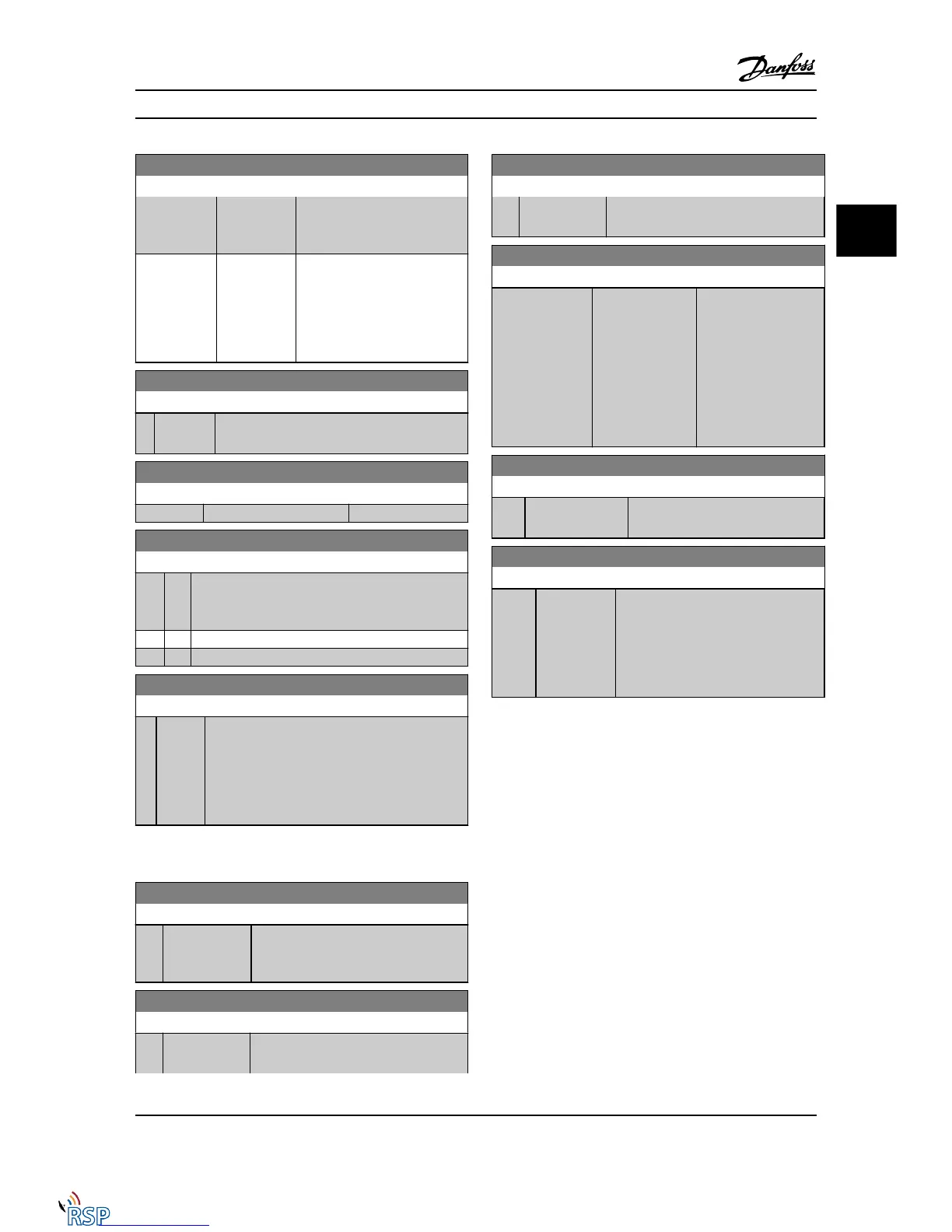
16-37 Inv. Max. Current
Range: Function:
connected motor. The data are
used for calculation of torque,
motor protection, etc.
Application
dependent*
[0.01 -
10000.00 A]
View the inverter maximum
current, which should match the
nameplate data on the
connected motor. The data are
used for calculation of torque,
motor protection, etc.
16-38 SL Controller State
Range: Function:
0* [0 - 100 ] View the state of the event under execution by
the SL controller.
16-39 Control Card Temp.
Range: Function:
0 °C* [0 - 100 °C]
16-40 Logging Buffer Full
Option: Function:
View whether the logging buffer is full (see parameter
group 15-1*). The logging buffer will never be full
when 15-13 Logging Mode is set to Log always [0].
[0] * No
[1] Yes
16-49 Current Fault Source
Range: Function:
0* [0 - 8 ] Value indicates source of current faults including
short circuit, overcurrent, and phase imbalance
(from left):
1-4 Inverter
5-8 Rectifier
0 No fault recorded
3.17.3 16-5* Ref. & Feedb.
16-50 External Reference
Range: Function:
0.0* [-200.0 -
200.0 ]
View the total reference, the sum of
digital, analog, preset, bus and freeze
references, plus catch-up and slow-down.
16-51 Pulse Reference
Range: Function:
0.0* [-200.0 -
200.0 ]
View the reference value from
programmed digital input(s). The readout
16-51 Pulse Reference
Range: Function:
can also reflect the impulses from an
incremental encoder.
16-52 Feedback [Unit]
Range: Function:
0.000 Reference-
FeedbackUnit*
[-999999.999 -
999999.999
ReferenceFeed-
backUnit]
View the feedback unit
resulting from the
selection of unit and
scaling in 3-00 Reference
Range, 3-01 Reference/
Feedback Unit,
3-02 Minimum Reference
and 3-03 Maximum
Reference.
16-53 Digi Pot Reference
Range: Function:
0.00* [-200.00 - 200.00 ] View the contribution of the digital
potentiometer to the actual reference.
16-57 Feedback [RPM]
Range: Function:
0 RPM* [-30000 -
30000 RPM]
Readout parameter where the actual
motor RPM from the feedback source
can be read in both closed-loop and
open-loop. The feedback source is
selected by 7-00 Speed PID Feedback
Source.
Parameter Descriptions FC 300 Programming Guide
MG33MD22 - VLT
®
is a registered Danfoss trademark 3-143
3
3

 Loading...


