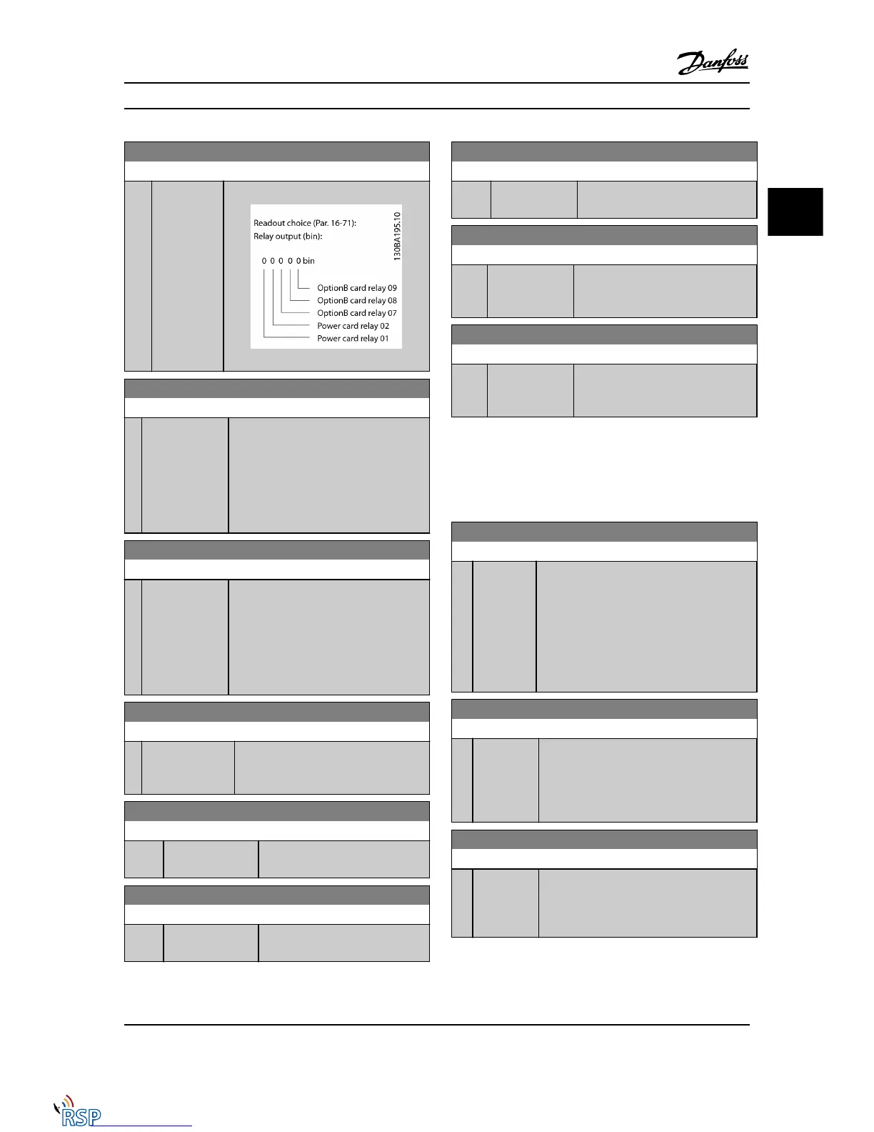
16-71 Relay Output [bin]
Range: Function:
0 * [0 - 511 ] View the settings of all relays.
16-72 Counter A
Range: Function:
0* [-2147483648 -
2147483647 ]
View the present value of Counter A.
Counters are useful as comparator
operands, see 13-10 Comparator Operand.
The value can be reset or changed either
via digital inputs (parameter group 5-1*) or
by using an SLC action (13-52 SL Controller
Action).
16-73 Counter B
Range: Function:
0* [-2147483648 -
2147483647 ]
View the present value of Counter B.
Counters are useful as comparator
operands (13-10 Comparator Operand).
The value can be reset or changed either
via digital inputs (parameter group 5-1*) or
by using an SLC action (13-52 SL Controller
Action).
16-74 Prec. Stop Counter
Range: Function:
0* [0 - 2147483647 ] Returns the actual counter value of
precise counter (1-84 Precise Stop Counter
Value).
16-75 Analog In X30/11
Range: Function:
0.000 * [-20.000 - 20.000 ] View the actual value at input
X30/11 of MCB 101.
16-76 Analog In X30/12
Range: Function:
0.000 * [-20.000 - 20.000 ] View the actual value at input
X30/12 of MCB 101.
16-77 Analog Out X30/8 [mA]
Range: Function:
0.000 * [0.000 - 30.000 ] View the actual value at input X30/8
in mA.
16-78 Analog Out X45/1 [mA]
Range: Function:
0.000* [0.000 - 30.000 ] View the actual value at output X45/1.
The value shown reflects the selection
in 6-70 Terminal X45/1 Output.
16-79 Analog Out X45/3 [mA]
Range: Function:
0.000* [0.000 - 30.000 ] View the actual value at output X45/3.
The value shown reflects the selection
in 6-80 Terminal X45/3 Output.
3.17.5 16-8* Serial communication bus &
FC Port
Parameters for reporting the BUS references and control
words.
16-80 Fieldbus CTW 1
Range: Function:
0 * [0 -
65535 ]
View the two-byte control word (CTW) received
from the bus master. Interpretation of the
control word depends on the Serial
communication bus option installed and the
control word profile selected in 8-10 Control
Profile.
For more information, please refer to the
relevant Serial communication bus manual.
16-82 Fieldbus REF 1
Range: Function:
0 * [-200 -
200 ]
View the two-byte word sent with the control
word form the bus master to set the reference
value.
For more information, refer to the relevant
serial communication bus manual.
16-84 Comm. Option STW
Range: Function:
0 * [0 - 65535 ] View the extended Serial communication bus
comm. option status word.
For more information, please refer to the
relevant Serial communication bus manual.
Parameter Descriptions FC 300 Programming Guide
MG33MD22 - VLT
®
is a registered Danfoss trademark 3-145
3
3

 Loading...


