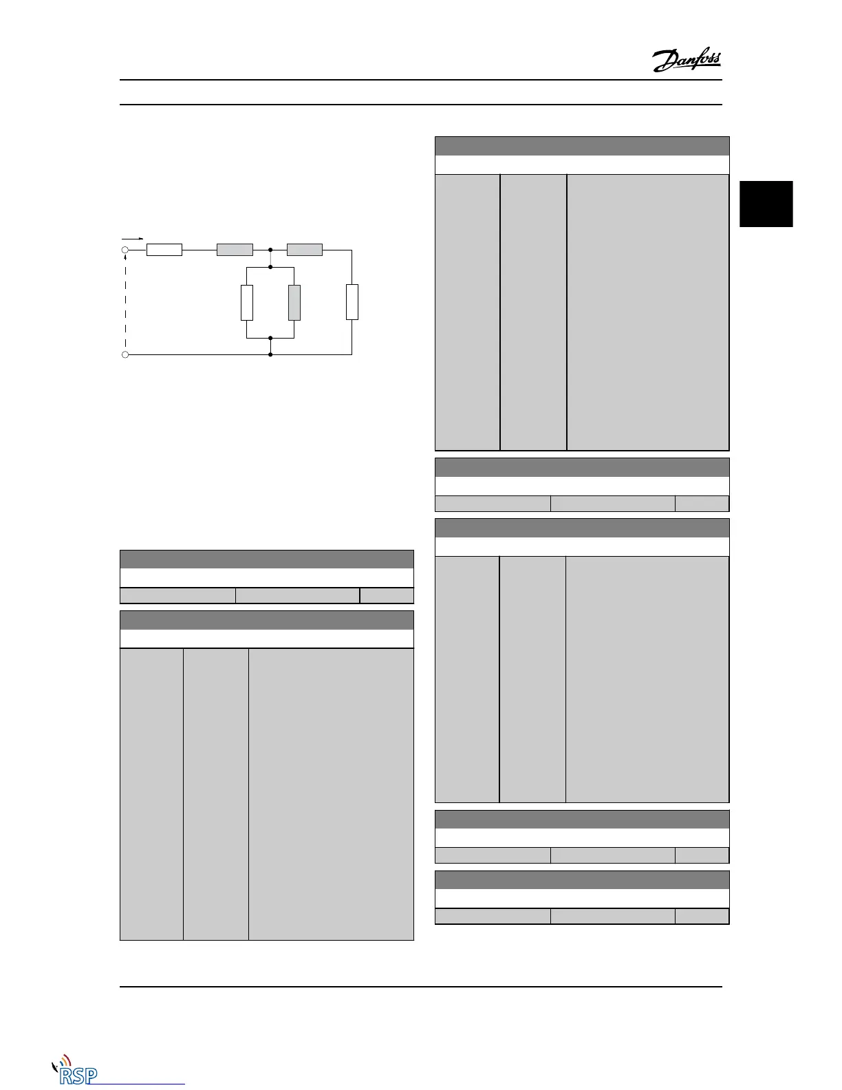
Figure 3.1 Motor equivalent diagram for an asynchronous
motor
NOTE!
A simple check of the X1 + Xh sum value is to divide the
line to line motor voltage by the sqrt(3) and divide this
value by the motor no load current. [VL-L/sqrt(3)]/I
NL
= X1
+ Xh. These values are important to properly magnetize
the motor. For high pole motors it is highly recommended
to perform this check.
1-30 Stator Resistance (Rs)
Range: Function:
Application dependent* [Application dependant]
1-31 Rotor Resistance (Rr)
Range: Function:
Application
dependent*
[Application
dependant]
Fine-tuning R
r
will improve shaft
performance. Set the rotor
resistance value using one of these
methods:
1. Run an AMA on a cold
motor. The Adjustable
frequency drive will
measure the value from
the motor. All compen-
sations are reset to 100%.
2. Enter the R
r
value
manually. Obtain the value
from the motor supplier.
3. Use the R
r
default setting.
The Adjustable frequency
drive establishes the
setting on the basis of the
motor nameplate data.
1-33 Stator Leakage Reactance (X1)
Range: Function:
Application
dependent*
[Application
dependant]
Set the stator leakage reactance of
the motor using one of these
methods:
1. Run an AMA on a cold
motor. The Adjustable
frequency drive will
measure the value from
the motor.
2. Enter the X
1
value
manually. Obtain the
value from the motor
supplier.
3. Use the X
1
default setting.
The Adjustable frequency
drive establishes the
setting on the basis of the
motor nameplate data.
1-34 Rotor Leakage Reactance (X2)
Range: Function:
Application dependent* [Application dependant]
1-35 Main Reactance (Xh)
Range: Function:
Application
dependent*
[Application
dependant]
Set the main reactance of the
motor using one of these methods:
1. Run an AMA on a cold
motor. The Adjustable
frequency drive will
measure the value from
the motor.
2. Enter the X
h
value
manually. Obtain the value
from the motor supplier.
3. Use the X
h
default setting.
The Adjustable frequency
drive establishes the
setting on the basis of the
motor nameplate data.
1-36 Iron Loss Resistance (Rfe)
Range: Function:
Application dependent* [Application dependant]
1-37 d-axis Inductance (Ld)
Range: Function:
Application dependent* [Application dependant]
Parameter Descriptions FC 300 Programming Guide
MG33MD22 - VLT
®
is a registered Danfoss trademark 3-17
3
3

 Loading...


