Par
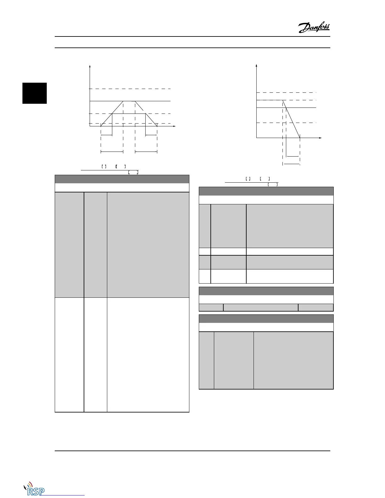
. 3 − 80 =
t
jog
s
x
n
s
RPM
Δ
log
speed
(
par
. 3 − 19
)
RPM
3-81 Quick Stop Ramp Time
Range: Function:
Application
dependent*
[0.01 -
3600.00
s]
Enter the quick stop ramp-down time,
i.e., the deceleration time from the
synchronous motor speed to 0 RPM.
Ensure that no resultant overvoltage
will arise in the inverter due to
regenerative operation of the motor
required to achieve the given ramp-
down time. Ensure also that the
generated current required to achieve
the given ramp-down time does not
exceed the current limit (set in
4-18 Current Limit). Quick stop is
activated by means of a signal on a
selected digital input, or via the serial
communication port.
Application
dependent*
[0.01 -
3600.00
s]
Bus only
Enter the quick stop ramp-down time,
i.e., the deceleration time from the
synchronous motor speed to 0 RPM.
Ensure that no resultant overvoltage
will arise in the inverter due to
regenerative operation of the motor
required to achieve the given ramp-
down time. Ensure also that the
generated current required to achieve
the given ramp-down time does not
exceed the current limit (set in
4-18 Current Limit). Quick stop is
activated by means of a signal on a
selected digital input, or via the serial
communication port.
Par
. 3 − 81 =
t
Qstop
s
x
n
s
RPM
Δ
jog
ref
(
par
. 3 − 19
)
RPM
3-82 Quick Stop Ramp Type
Option: Function:
Select the ramp type, depending on
requirements for acceleration and
deceleration. A linear ramp will give
constant acceleration during ramping. An
S-ramp will give non-linear acceleration,
compensating for jerk in the application.
[0] * Linear
[1] S-ramp Const
Jerk
[2] S-ramp Const
Time
3-83 Quick Stop S-ramp Ratio at Decel. Start
Range: Function:
50 %* [Application dependant]
3-84 Quick Stop S-ramp Ratio at Decel. End
Range: Function:
50 %* [Application
dependant]
Enter the proportion of the total
ramp-down time (3-42 Ramp 1 Ramp
Down Time) where the deceleration
torque decreases. The larger the
percentage value, the greater the jerk
compensation achieved, and thus the
lower the torque jerks in the
application.
3.5.8 3-9* Digital Pot. meter
The digital potentiometer function allows the user to
increase or decrease the actual reference by adjusting the
set-up of the digital inputs using the functions Increase,
Parameter Descriptions FC 300 Programming Guide
3-42 MG33MD22 - VLT
®
is a registered Danfoss trademark
3
3

 Loading...


