8-08 Readout Filtering
The function is used if the speed feedback value readouts on
serial communication bus are fluctuating. Select filtered if the
function is required. A power-cycle is required for changes to
take effect.
Option: Function:
16-12 Motor Voltage
16-14 Motor Current
16-16 Torque [Nm]
16-17 Speed [RPM]
16-22 Torque [%]
16-25 Torque [Nm] High
3.10.2 8-1* Ctrl. Word Settings
8-10 Control Word Profile
Select the interpretation of the control and status words
corresponding to the installed Serial communication bus. Only
the selections valid for the Serial communication bus installed in
slot A will be visible in the LCP display.
For guidelines in selection of FC profile [0] and PROFIdrive profile
[1] please refer to the Serial communication via RS 485 Interface
section.
For additional guidelines in the selection of PROFIdrive profile [1],
ODVA [5] and CANopen DSP 402 [7], please refer to the
Instruction Manual for the installed Serial communication bus.
Option: Function:
[0] * FC profile
[1] PROFIdrive profile
[5] ODVA
[7] CANopen DSP 402
[8] MCO
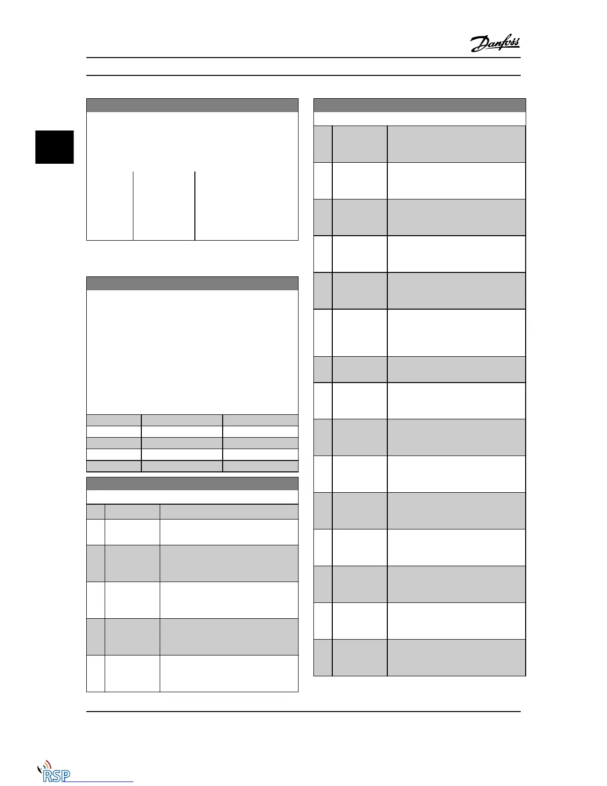
8-13 Configurable Status Word STW
Option: Function:
[0] No function The input is always low.
[1] * Profile Default Depended on the profile set in
8-10 Control Profile.
[2] Alarm 68 Only The input will go high whenever Alarm 68
is active and will go low whenever no
alarm 68 is active
[3] Trip excl Alarm
68
The input will go high whenever Trip on
other alarms is active, and then Alarm 68
is active.
[10] T18 DI status The input will go high whenever T18 has
24 V and will go low whenever T18 has 0
V.
[11] T19 DI status The input will go high whenever T19 has
24 V and will go low whenever T19 has 0
V.
8-13 Configurable Status Word STW
Option: Function:
[12] T27 DI status The input will go high whenever T27 has
24 V and will go low whenever T27 has 0
V.
[13] T29 DI status The input will go high whenever T29 has
24 V and will go low whenever T29 has 0
V.
[14] T32 DI status The input will go high whenever T32 has
24 V and will go low whenever T32 has 0
V.
[15] T33 DI status The input will go high whenever T33 has
24 V and will go low whenever T33 has 0
V.
[16] T37 DI status The input will go high whenever T37 has
0 V and will go low whenever T37 has 24
V
[21] Thermal
warning
The thermal warning turns on when the
temperature exceeds the limit in the
motor, the Adjustable frequency drive, the
brake resistor, or the thermistor.
[30] Brake fault
(IGBT)
Will go high when the brake IGBT is short-
circuited.
[40] Out of ref
range
If Comparator 0 is evaluated as TRUE, the
input will go high. Otherwise, it will be
low.
[60] Comparator 0 If Comparator 0 is evaluated as TRUE, the
input will go high. Otherwise, it will be
low.
[61] Comparator 1 If Comparator 1 is evaluated as TRUE, the
input will go high. Otherwise, it will be
low.
[62] Comparator 2 If Comparator 2 is evaluated as TRUE, the
input will go high. Otherwise, it will be
low.
[63] Comparator 3 If Comparator 3 is evaluated as TRUE, the
input will go high. Otherwise, it will be
low.
[64] Comparator 4 If Comparator 4 is evaluated as TRUE, the
input will go high. Otherwise, it will be
low.
[65] Comparator 5 If Comparator 5 is evaluated as TRUE, the
input will go high. Otherwise, it will be
low.
[70] Logic Rule 0 If Logic Rule 0 is evaluated as TRUE, the
input will go high. Otherwise, it will be
low.
Parameter Descriptions FC 300 Programming Guide
3-86 MG33MD22 - VLT
®
is a registered Danfoss trademark
3
3

 Loading...


