8-05 End-of-Timeout Function
Option: Function:
Select the action after receiving a valid
control word following a timeout. This
parameter is active only when 8-04 Control
Timeout Function is set to [Set-up 1-4].
[0] Hold set-up
Retains the set-up selected in 8-04 Control
Timeout Function and displays a warning,
until 8-06 Reset Control Timeout toggles. Then
the Adjustable frequency drive resumes its
original set-up.
[1] * Resume set-
up
Resumes the set-up active prior to the
timeout.
8-06 Reset Control Word Timeout
This parameter is active only when Hold set-up [0] has been
selected in 8-05 End-of-Timeout Function.
Option: Function:
[0] * Do not reset
Retains the set-up specified in 8-04 Control
Word Timeout Function, following a control
word timeout.
[1] Do reset Returns the Adjustable frequency drive to the
original set-up following a control word
timeout. The Adjustable frequency drive
performs the reset and then immediately
reverts to the Do not reset [0] setting
8-07 Diagnosis Trigger
Option: Function:
This parameter enables and controls the
Adjustable frequency drive diagnosis function
and permits expansion of the diagnosis data to
24 byte.
NOTE!
This is only valid for Profibus.
-
Disable [0]: Do not send extended
diagnosis data even if they appear in
the Adjustable frequency drive.
-
Trigger on alarms [1]: Send extended
diagnosis data when one or more
alarms appear in alarm 16-90 Alarm
Word or 9-53 Profibus Warning Word.
-
Trigger alarms/warn. [2]: Send extended
diagnosis data if one or more alarms or
warnings appear in alarm 16-90 Alarm
Word, 9-53 Profibus Warning Word, or
warning 16-92 Warning Word.
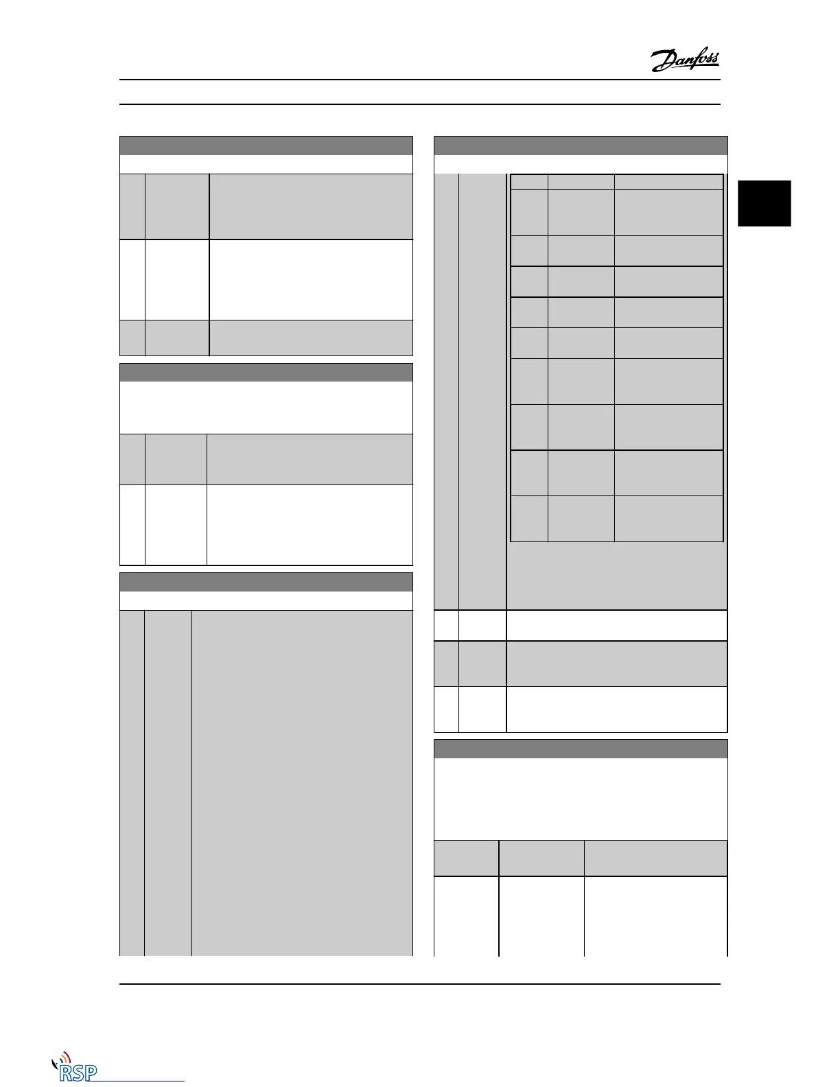
The content of the extended diagnosis frame is
as follows:
8-07 Diagnosis Trigger
Option: Function:
Byte Content Description
0–5 Standard DP
Diagnose
Data
Standard DP Diagnose
Data
6 PDU length
xx
Header of extended
diagnostic data
7 Status type =
0x81
Header of extended
diagnostic data
8 Slot = 0 Header of extended
diagnostic data
9 Status info =
0
Header of extended
diagnostic data
10–13 VLT
16-92 Warnin
g Word
VLT warning word
14–17
VLT
16-03 Status
Word
VLT status word
18–21 VLT
16-90 Alarm
Word
VLT alarm word
22–23
VLT
9-53 Profibus
Warning Word
Communication
warning word
(Profibus)
Enabling diagnosis may cause increased bus
traffic. Diagnosis functions are not supported by
all serial communication bus types.
[0]
*
Disable
[1] Trigger
on
alarms
[2] Trigger
alarm/
warn.
8-08 Readout Filtering
The function is used if the speed feedback value readouts on
serial communication bus are fluctuating. Select filtered if the
function is required. A power-cycle is required for changes to
take effect.
Option: Function:
[0] * Motor Data Std-
Filt.
Select [0] for normal bus
readouts.
[1] Motor Data LP-
Filter
Select [1] for filtered bus
readouts of the following
parameters:
16-10 Power [kW]
16-11 Power [hp]
Parameter Descriptions FC 300 Programming Guide
MG33MD22 - VLT
®
is a registered Danfoss trademark 3-85
3
3

 Loading...


