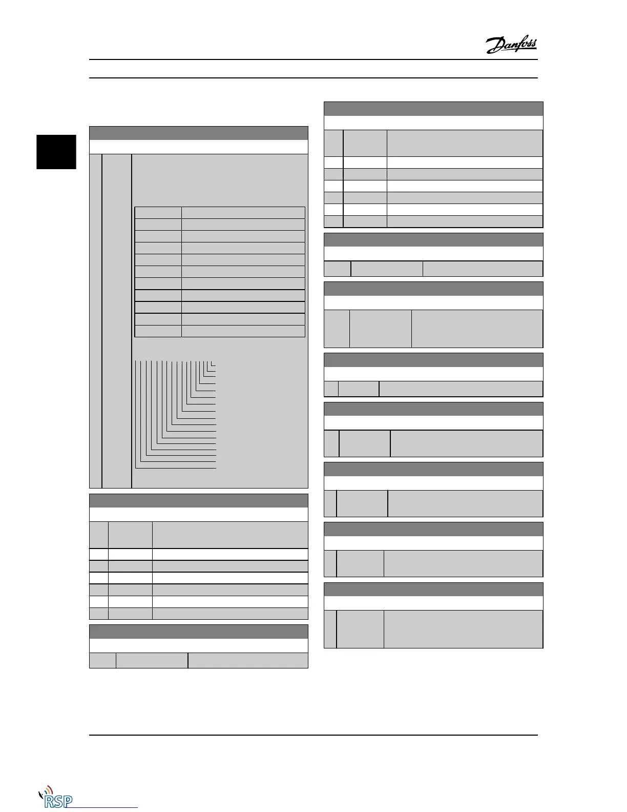
3.17.4 16-6* Inputs & Outputs
16-60 Digital Input
Range: Function:
0
*
[0 -
1023 ]
View the signal states from the active digital inputs.
Example: Input 18 corresponds to bit no. 5, ‘0’ = no
signal, ‘1’ = connected signal. Bit 6 works in the
opposite way, on = '0', off = '1' (safe stop input).
Bit 0 Digital input term. 33
Bit 1 Digital input term. 32
Bit 2 Digital input term. 29
Bit 3 Digital input term. 27
Bit 4 Digital input term. 19
Bit 5 Digital input term. 18
Bit 6 Digital input term. 37
Bit 7 Digital input GP I/O term. X30/4
Bit 8 Digital input GP I/O term. X30/3
Bit 9 Digital input GP I/O term. X30/2
Bit 10-63 Reserved for future terminals
16-61 Terminal 53 Switch Setting
Option: Function:
View the setting of input terminal 53. Current
= 0; Voltage = 1.
[0] * Current
[1] Voltage
[2] Pt 1000 [°C]
[3] Pt 1000 [°F]
[4] Ni 1000 [°C]
[5] Ni 1000 [°F]
16-62 Analog Input 53
Range: Function:
0.000* [-20.000 - 20.000 ] View the actual value at input 53.
16-63 Terminal 54 Switch Setting
Option: Function:
View the setting of input terminal 54. Current
= 0; Voltage = 1.
[0] * Current
[1] Voltage
[2] Pt 1000 [°C]
[3] Pt 1000 [°F]
[4] Ni 1000 [°C]
[5] Ni 1000 [°F]
16-64 Analog Input 54
Range: Function:
0.000* [-20.000 - 20.000 ] View the actual value at input 54.
16-65 Analog Output 42 [mA]
Range: Function:
0.000* [0.000 - 30.000 ] View the actual value at output 42 in
mA. The value shown reflects the
selection in 6-50 Terminal 42 Output.
16-66 Digital Output [bin]
Range: Function:
0* [0 - 15 ] View the binary value of all digital outputs.
16-67 Pulse Input #29 [Hz]
Range: Function:
0 * [0 - 130000 ] View the actual frequency rate on terminal
29.
16-68 Freq. Input #33 [Hz]
Range: Function:
0* [0 - 130000 ] View the actual value of the frequency
applied at terminal 33 as an impulse input.
16-69 Pulse Output #27 [Hz]
Range: Function:
0* [0 - 40000 ] View the actual value of pulses applied to
terminal 27 in digital output mode.
16-70 Pulse Output #29 [Hz]
Range: Function:
0* [0 - 40000 ] View the actual value of pulses at terminal 29
in digital output mode.
This parameter is available for FC 302 only.
Parameter Descriptions FC 300 Programming Guide
3-144 MG33MD22 - VLT
®
is a registered Danfoss trademark
3
3

 Loading...


