5-40 Function Relay
Array [9]
(Relay 1 [0], Relay 2 [1], Relay 3 [2] (MCB 113), Relay 4 [3] (MCB
113), Relay 5 [4] (MCB 113), Relay 6 [5] (MCB 113), Relay 7 [6]
(MCB 105), Relay 8 [7] (MCB 105), Relay 9 [8] (MCB 105))
Option: Function:
[75] Logic rule 5 See parameter group 13-4*(Smart
Logic Control). If Logic Rule 5 in SLC
is TRUE, the output will go high.
Otherwise, it will be low.
[80] SL digital output A
See 13-52 SL Controller Action. Output
A is low on Smart Logic Action [32].
Output A is high on Smart Logic
Action [38].
[81] SL digital output B
See 13-52 SL Controller Action. Output
B is low on Smart Logic Action [33].
Output B is high on Smart Logic
Action [39].
[82] SL digital output C
See 13-52 SL Controller Action. Output
C is low on Smart Logic Action [34].
Output C is high on Smart Logic
Action [40].
[83] SL digital output D
See 13-52 SL Controller Action. Output
D is low on Smart Logic Action [35].
Output D is high on Smart Logic
Action [41]
[84] SL digital output E
See 13-52 SL Controller Action. Output
E is low on Smart Logic Action [36].
Output E is high on Smart Logic
Action [42].
[85] SL digital output F
See 13-52 SL Controller Action. Output
F is low on Smart Logic Action [37].
Output F is high on Smart Logic
Action [43].
[120] Local ref active
Output is high when 3-13 Reference
Site = [2] Local or when
3-13 Reference Site = [0] Linked to
hand auto at the same time as the
LCP is in [Hand on] mode.
5-40 Function Relay
Array [9]
(Relay 1 [0], Relay 2 [1], Relay 3 [2] (MCB 113), Relay 4 [3] (MCB
113), Relay 5 [4] (MCB 113), Relay 6 [5] (MCB 113), Relay 7 [6]
(MCB 105), Relay 8 [7] (MCB 105), Relay 9 [8] (MCB 105))
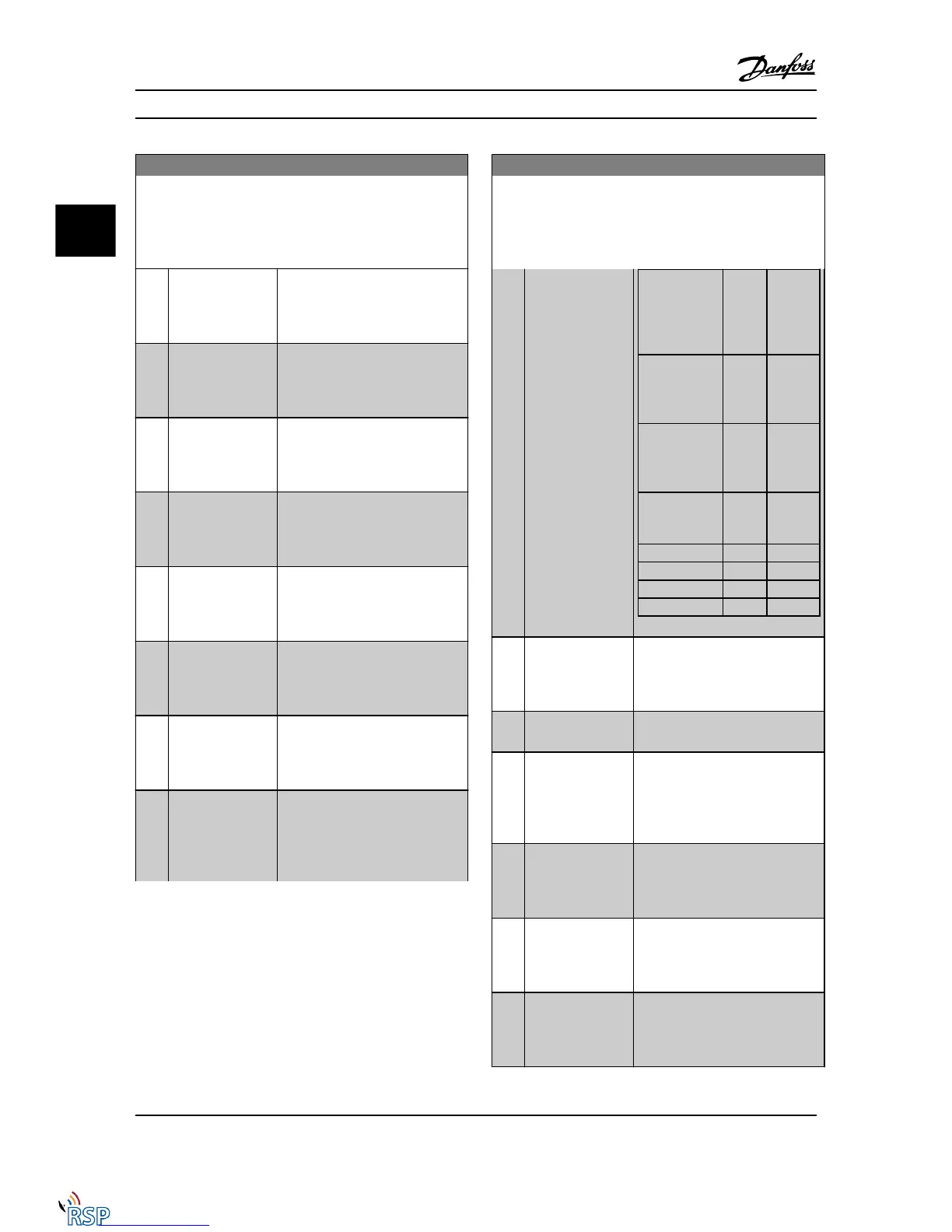
Option: Function:
Reference site
set in
3-13 Reference
Site
Local
referen
ce
active
[120]
Remote
reference
active
[121]
Reference site:
Local
3-13 Reference
Site [2]
1 0
Reference site:
Remote
3-13 Reference
Site [1]
0 1
Reference site:
Linked to Hand/
Auto
Hand 1 0
Hand -> off 1 0
Auto -> off 0 0
Auto 0 1
[121] Remote ref active
Output is high when 3-13 Reference
Site = Remote [1] or Linked to hand/
auto [0] while the LCP is in [Auto on]
mode. See above.
[122] No alarm Output is high when no alarm is
present.
[123] Start command
activ
Output is high when the Start
command high (i.e., via digital input,
bus connection or [Hand on] or
[Auto on]), and a Stop has been last
command.
[124] Running reverse Output is high when the Adjustable
frequency drive is running counter
clockwise (the logical product of the
status bits ‘running’ AND ‘reverse’).
[125] Drive in hand mode Output is high when the Adjustable
frequency drive is in [Hand on]
mode (as indicated by the LED
above [Hand on]).
[126] Drive in auto mode Output is high when the Adjustable
frequency drive is in ‘Auto’ mode (as
indicated by LED on above [Auto
on]).
Parameter Descriptions FC 300 Programming Guide
3-62 MG33MD22 - VLT
®
is a registered Danfoss trademark
3
3

 Loading...


