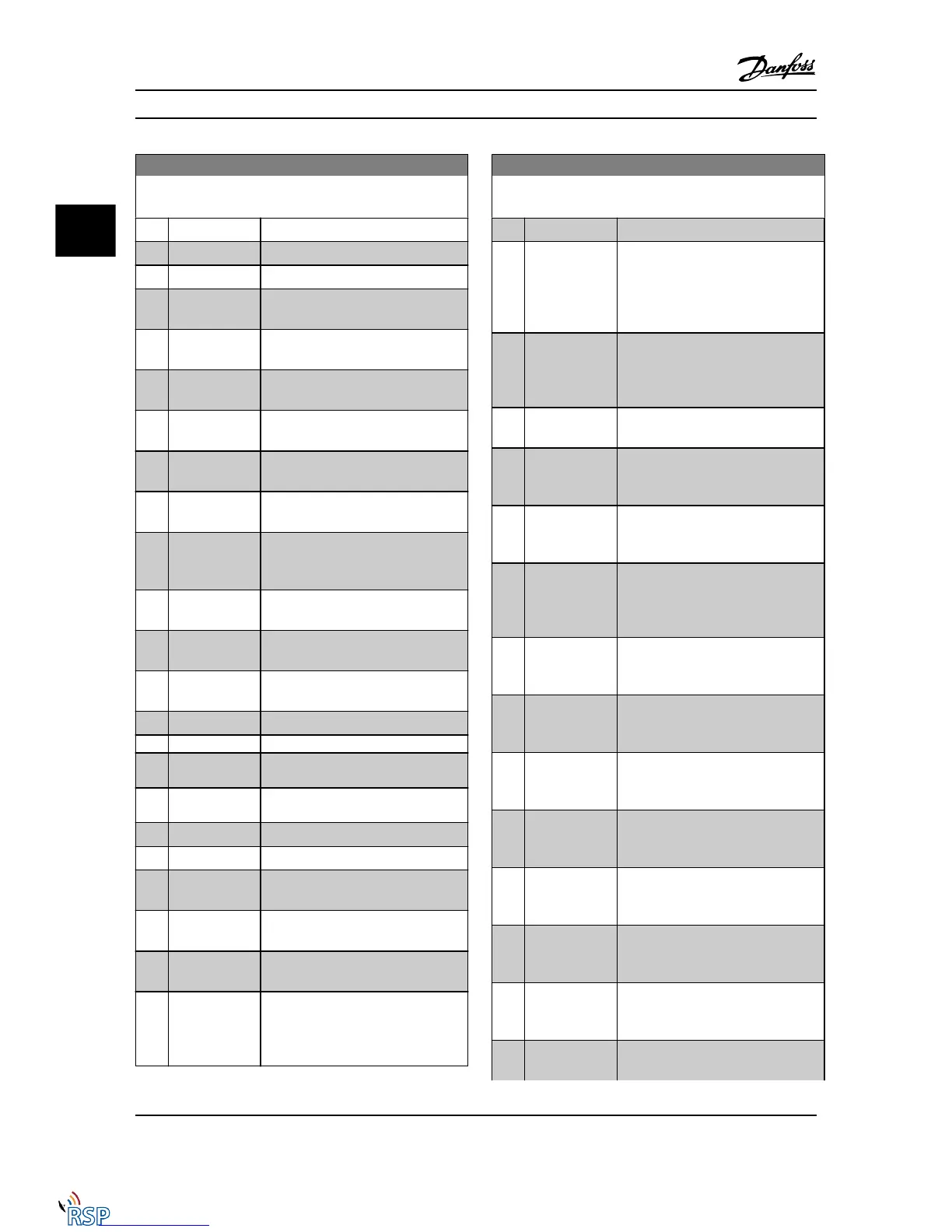
13-10 Comparator Operand
Array [6]
Option: Function:
[6] Motor power
Motor power [6] [kW] or [hp]
[7] Motor voltage
Motor voltage [7] [V]
[8] DC-link voltage
DC-link voltage [8] [V]
[9] Motor thermal
Motor thermal [9] Expressed as a
percentage.
[10] Drive thermal
VLT thermal [10] Expressed as a
percentage.
[11] Heat sink temp.
Heatsink temp [11] Expressed as a
percentage.
[12] Analog input
AI53
Analog input AI53 [12] Expressed as a
percentage.
[13] Analog input
AI54
Analog input AI54 [13] Expressed as a
percentage.
[14] Analog input
AIFB10
Analog input AIFB10 [14] [V]. AIFB10 is
internal 10V supply.
[15] Analog input
AIS24V
Analog input AIS24V [15] [V] Analog
input AICCT [17] [°]. AIS24V is switch
mode power supply: SMPS 24V.
[17] Analog input
AICCT
Analog input AICCT [17] [°]. AICCT is
control card temperature.
[18] Pulse input FI29
Pulse input FI29 [18] Expressed as a
percentage.
[19] Pulse input FI33
Pulse input FI33 [19] Expressed as a
percentage.
[20] Alarm number
Alarm number [20] The error number.
[21] Warning number
[22] Analog input
x30 11
[23] Analog input
x30 12
[30] Counter A
Counter A [30] Number of counts
[31] Counter B
Counter B [31] Number of counts
[50] FALSE
False [50] Enters the fixed value of false
in the comparator.
[51] TRUE
True [51] Enters the fixed value of true
in the comparator.
[52] Control ready
Control ready [52] The control board
receives supply voltage
[53] Drive ready
Drive ready [53] The Adjustable
frequency drive is ready for operation
and applies a supply signal on the
control board.
13-10 Comparator Operand
Array [6]
Option: Function:
[54] Running
Running [54] The motor is running.
[55] Reversing
Reversing [55] The output is high when
the Adjustable frequency drive is
running counter clockwise (the logical
product of the status bits “running”
AND “reverse”)
[56] In range
In range [56] The motor is running
within the programmed current and
speed ranges set in 4-50 Warning
Current Low to 4-53 Warning Speed High.
[60] On reference
On reference [60] The motor is running
on reference.
[61] Below reference,
low
Below reference, low [61] The motor is
running below the value given in
4-54 Warning Reference Low
[62] Above ref, high
Above reference, high [62] The motor is
running above the value given in
4-55 Warning Reference High
[65] Torque limit
Torque limit [65] The torque limit, set in
4-16 Torque Limit Motor Mode or
4-17 Torque Limit Generator Mode, has
been exceeded.
[66] Current limit
Current limit [66] The motor current
limit, set in 4-18 Current Limit, has been
exceeded.
[67] Out of current
range
Out of current range [67] The motor
current is outside the range set in
4-18 Current Limit.
[68] Below I low
Below I low [68] The motor current is
lower than set in 4-50 Warning Current
Low.
[69] Above I high
Above I high [69] The motor current is
higher than set in 4-51 Warning Current
High.
[70] Out of speed
range
Out of speed range [70] The speed is
outside the range set in 4-52 Warning
Speed Low and 4-53 Warning Speed High.
[71] Below speed low
Below speed low [71] The output speed
is lower than the setting in
4-52 Warning Speed Low.
[72] Above speed
high
Above speed high [72] The output speed
is higher than the setting in
4-53 Warning Speed High.
[75] Out of feedb.
range
Out of feedb. Range [75] The feedback is
outside the range set in 4-56 Warning
Parameter Descriptions FC 300 Programming Guide
3-114 MG33MD22 - VLT
®
is a registered Danfoss trademark
3
3

 Loading...


