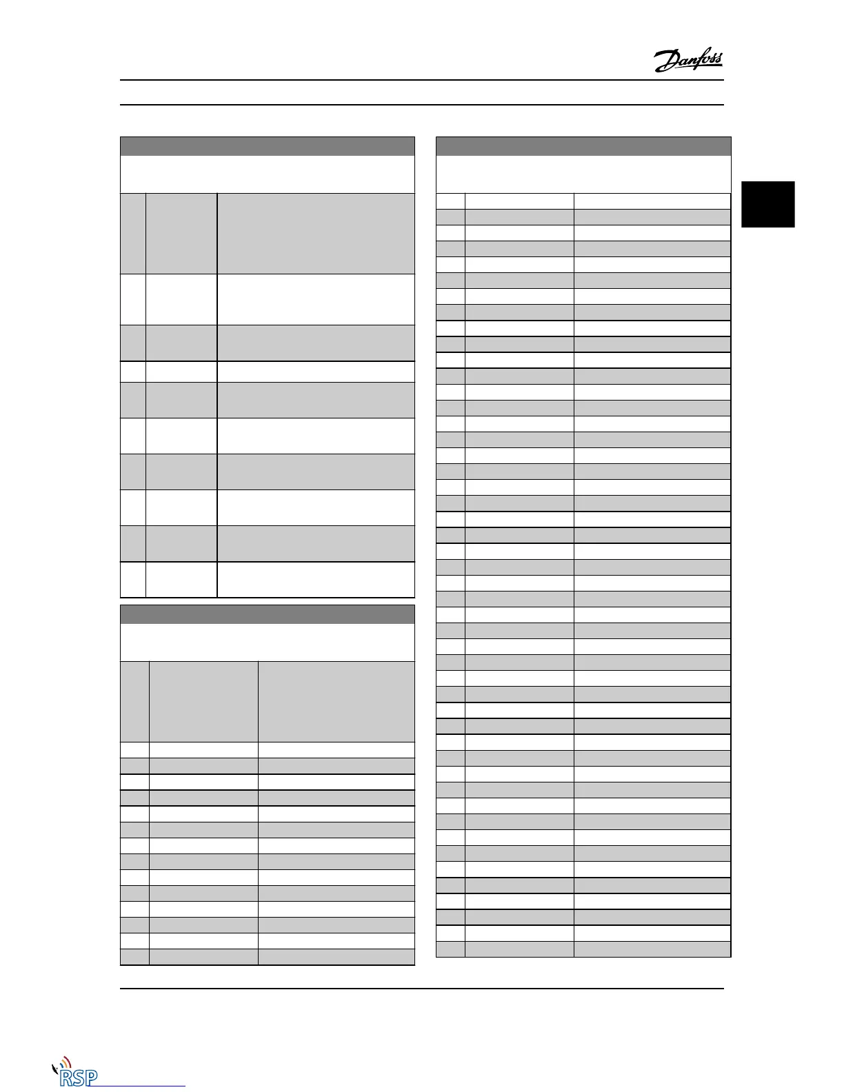
13-41 Logic Rule Operator 1
Array [6]
Option: Function:
Select the first logical operator to use on
the Boolean inputs from 13-40 Logic Rule
Boolean 1 and 13-42 Logic Rule Boolean 2.
[13-**] signifies the Boolean input of
parameter group 13-**.
[0] * DISABLED
Ignores 13-42 Logic Rule Boolean 2,
13-43 Logic Rule Operator 2, and 13-44 Logic
Rule Boolean 3.
[1] AND Evaluates the expression [13-40] AND
[13-42].
[2] OR evaluates the expression [13-40] OR [13-42].
[3] AND NOT evaluates the expression [13-40] AND NOT
[13-42].
[4] OR NOT evaluates the expression [13-40] OR NOT
[13-42].
[5] NOT AND evaluates the expression NOT [13-40] AND
[13-42].
[6] NOT OR evaluates the expression NOT [13-40] OR
[13-42].
[7] NOT AND NOT evaluates the expression NOT [13-40] AND
NOT [13-42].
[8] NOT OR NOT evaluates the expression NOT [13-40] OR
NOT [13-42].
13-42 Logic Rule Boolean 2
Array [6]
Option: Function:
[0] * False Select the second Boolean (TRUE
or FALSE) input for the selected
logic rule. See 13-01 Start Event
([0] - [61]) and 13-02 Stop Event
([70] - [75]) for further description.
[1] True
[2] Running
[3] In range
[4] On reference
[5] Torque limit
[6] Current limit
[7] Out of current range
[8] Below I low
[9] Above I high
[10] Out of speed range
[11] Below speed low
[12] Above speed high
[13] Out of feedb. range
[14] Below feedb. low
13-42 Logic Rule Boolean 2
Array [6]
Option: Function:
[15] Above feedb. high
[16] Thermal warning
[17] Mains out of range
[18] Reversing
[19] Warning
[20] Alarm (trip)
[21] Alarm (trip lock)
[22] Comparator 0
[23] Comparator 1
[24] Comparator 2
[25] Comparator 3
[26] Logic rule 0
[27] Logic rule 1
[28] Logic rule 2
[29] Logic rule 3
[30] SL Time-out 0
[31] SL Time-out 1
[32] SL Time-out 2
[33] Digital input DI18
[34] Digital input DI19
[35] Digital input DI27
[36] Digital input DI29
[37] Digital input DI32
[38] Digital input DI33
[39] Start command
[40] Drive stopped
[41] Reset Trip
[42] Auto-reset Trip
[43] Ok key
[44] Reset key
[45] Left key
[46] Right key
[47] Up key
[48] Down key
[50] Comparator 4
[51] Comparator 5
[60] Logic rule 4
[61] Logic rule 5
[70] SL Time-out 3
[71] SL Time-out 4
[72] SL Time-out 5
[73] SL Time-out 6
[74] SL Time-out 7
[75] Start command given
[76] Digital input x30/2
[77] Digital input x30/3
[78] Digital input x30/4
[79] Digital input x46/1
Parameter Descriptions FC 300 Programming Guide
MG33MD22 - VLT
®
is a registered Danfoss trademark 3-121
3
3

 Loading...


